Don't hurry. The mistakes you will make when hurrying will compensate for the time you thought to win. Or it may take even longer...
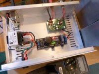
Tip: drill the encasing before the boards are finished (count with the caps of the PSU sticking out) and mount switches, RCA/BNC/ IEC input etc beforehand. It won't be the first time that parts are suddenly "in the way" of the boards. Try to keep 230 V AC as far away from the boards as possible. Mount L+R RCA's as far away as possible from 230 V AC. In other words: place boards and parts in the case and try to route everything as optimal as possible. Costs a few monutes but can save quite some time later on. Please see the picture as that member did an excellent layout.
Tip: drill the encasing before the boards are finished (count with the caps of the PSU sticking out) and mount switches, RCA/BNC/ IEC input etc beforehand. It won't be the first time that parts are suddenly "in the way" of the boards. Try to keep 230 V AC as far away from the boards as possible. Mount L+R RCA's as far away as possible from 230 V AC. In other words: place boards and parts in the case and try to route everything as optimal as possible. Costs a few monutes but can save quite some time later on. Please see the picture as that member did an excellent layout.
Attachments
Last edited:
I will address the lack of sufficient solder on TR1. I don`t think it`s as bad as it looks in the picture though. ;-)
Tonight I will sit down and verify every part with the BOM and schematic before I solder it, not after. 🙂 We have a saying in Norway; "Hastverk er lastverk", meaning something like; if you hurry to much, you will make mistakes, which will take more time to correct, than if you took your time and made it right the first time.
Usually I do take my time to make sure I do everything correct, but I think the culprit to my mistake yesterday might be what`s in the top of the pictures I posted. ;-)
The case that I`m planning to put it in, is 9"x5"x2", so I`ll have reasonable space to seperate power from signal, and I also have some thick copper sheeting laying around at work, so I can also use that to seperate the case into "power" and "signal" sections.
Regards
- Bjørn
HI,
You should read the first post of this thread by Bob as he lists all the issues to avoid and give also excellent "how to" and a link from the voltage values by Korben69 to check before switch on (usefull to see shortcuts, cold joints, especially for the LDO regs !)
regards
P.S : sometimes I wear glasses...
"Hastverk er lastverk"
"Haastige spoed is zelden goed" over here, meaning hurrying rarely delivers quality work....I take "lastverk" means extra work ?
Eldam: I have the entire first post, and Korben's pictures printed, and sitting on my desk to use as a reference. ;-) But I'll blame yesterdays errors on the pilsner, causing impaired judgement and elevated belief in own skill and ability :-D
JP: you are correct, it means extra work/hazzle.
Regards
- Bjørn
JP: you are correct, it means extra work/hazzle.
Regards
- Bjørn
I have listened to a Subbu 3 at a member's place (Vgeorge) for a couple of days. Very nice work guys. It had a Reflektor-D as a 5V reg. Musical and open result. No bumps or harshness or darkness, nice flow. Could not compete to his (well sorted out and expensive) TT for immediacy and vividness, sense of scale and rhythm, midrange and hf dynamics on good vinyl records, but for digital it was very good. I think that those (apparent) differences are rooted in the way the mediums are manipulated in the mastering, not so much in the electronics. Badly cut LPs and below par TTs are many nonetheless.
Thanks Salas, it is a good DAC but no way it can compete with very good cut LP's played on very good analog equipment. But which DAC can ? 😉 I think we succeeded in getting a good result with a low cost simple digital design. We also understood thinking like we do will not be commercially viable as there will be no significantly better SPDIF version to make.... OK including an on board SPDIF transformer for SB Touch people would be nice.
BTW I googled for Reflektor-D but could not find what that is. The original PSU was tested recently and turned out to be quite good too (10 uV RMS noise AFAIK). Some members even mailed me that it could compete with your shunt regs. Not that I believed that of course ... 😀
BTW I googled for Reflektor-D but could not find what that is. The original PSU was tested recently and turned out to be quite good too (10 uV RMS noise AFAIK). Some members even mailed me that it could compete with your shunt regs. Not that I believed that of course ... 😀
Last edited:
BTW I googled for Reflektor-D but could not find what that is.
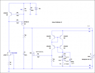
Its a bit of an obscure shunt reg of mine which has been going on point to point only by very few members. Its easy to make steady with just two LEDs reference. Based on low Rbb' BJTs current mirror and TTL output MOSFET with low capacitance parasitics under low VDS. A member from Japan was especially keen on exploiting its cooperation with digital circuits. Was giving him ideas for that and he was testing. I have in mind to test a pcb for it soon because its maybe a pity its not accessible to many for so long.
Attachments
The original PSU was tested recently and turned out to be quite good too (10 uV RMS noise AFAIK). Some members even mailed me that it could compete with your shunt regs. Not that I believed that of course ... 😀
Its a matter of synergy and integration, I am not sure what is best for what, I trust the members word for that. I made those circuits for general use and as an alternative to series ones so we can have more toys to play. 🙂
Had an apportunity to compare today Subbu V3's PSU with one of my friends B1 PSU. DAC being the same.
SQ with Subbu PSU was much better. Bass was much deeper and crisp, soundstage was wider, Treble were much livlier.
Good job JP and Subbu. THANKS !!!
SQ with Subbu PSU was much better. Bass was much deeper and crisp, soundstage was wider, Treble were much livlier.
Good job JP and Subbu. THANKS !!!
Success!!
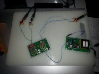
And another one is playing sweet music!! 😀
Just connected ghetto-style to my "test-rig" for now, but it sounds promising. 🙂
Now to give it a test on my main system, and then put it into it's chassis.
Regards
- Bjørn
And another one is playing sweet music!! 😀
Just connected ghetto-style to my "test-rig" for now, but it sounds promising. 🙂
Now to give it a test on my main system, and then put it into it's chassis.
Regards
- Bjørn
Attachments

Good ! I would recommend to use the 1 µF Wima MKS2 in 2,5 mm pitch for C32. When you put the boards in a case please try to keep wiring to the L+R RCA and SPDIF BNC connector short (yeah, 75 Ohm BNC really is better for SPDIF both at the sending and receiving ends of course). Also carefully plan how you will position the PSU and 230 V AC wiring. Let me know what the other fellow Brillegeits think of it.
Last edited:
Had an apportunity to compare today Subbu V3's PSU with one of my friends B1 PSU. DAC being the same.
SQ with Subbu PSU was much better. Bass was much deeper and crisp, soundstage was wider, Treble were much livlier.
Good job JP and Subbu. THANKS !!!
Thanks for reporting. I never would have thought our dinosaur reg would perform better than a Pass design.
Last edited:
Good ! I would recommend to use the 1 µF Wima MKS2 in 2,5 mm pitch for C32. When you put the boards in a case please try to keep wiring to the L+R RCA and SPDIF BNC connector short (yeah, 75 Ohm BNC really is better for SPDIF both at the sending and receiving ends of course). Also carefully plan how you will position the PSU and 230 V AC wiring. Let me know what the other fellow Brillegeits think of it.
So you mean switching the present c35 with a 2,5mm-pitched at position c32? I shall put it on my next order from mouser. 😉
I will be changing the SPDIF-connector to BNC when it goes in the chassis, I just haven't gotten to the task of adding BNC to my sources yet. So temporary it is RCA. BTW; any advice on thin 75Ohm coax-cable for internal cabling? All I have at home is RG59 which is too thick to get into the molex connectors..
I work with industrial-automation, so I am all too aware of the troubles that can occur when routing signal- and power-cabling too close(it has caused numerous hours of swearing and cursing, only to find that the cable-monkey does not understand how interference works...) So I will take great care when placing components and wiring in the chassis. 😉
Regards
- Bjørn
Yes, desolder the large 1 µF cap and replace it for a 2,5 mm 1 µF Wima MKS2 if you like. Do listen if you hear a difference or not but only if the DAC has played some hours. It needs a few days to settle.
RG179 is nice thin 75 Ohm cable but if you keep it very short just the wires you use now (non twisted) are OK too.
RG179 is nice thin 75 Ohm cable but if you keep it very short just the wires you use now (non twisted) are OK too.
I don't think Nelson included the PSU in the B1 article, so not a Nelson design for sure.
From the look of the PSU PCB, it looks like a relatively generic LM317 + LM337 implementation. JP, FWIW, I didn't even bother to confirm your dinosaur reg beats this vanilla LM317 implementation hands down many full moons ago 🙂 Your reg is even better than a LM317 with a capacitance multiplier!!
From the look of the PSU PCB, it looks like a relatively generic LM317 + LM337 implementation. JP, FWIW, I didn't even bother to confirm your dinosaur reg beats this vanilla LM317 implementation hands down many full moons ago 🙂 Your reg is even better than a LM317 with a capacitance multiplier!!
- Home
- Source & Line
- Digital Line Level
- Build thread - building the Subbu DAC V3 SE