I'm pretty sure Jan (JBdV) is hoping to get a heatsink too. There's got to be a few people out there who would be interested in the sink, especially now that we see how clean of a solution it is.
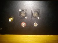
yeah he emailed me about fets too, but i havent heard back from him in response to my reply; busy with work i guess. using threaded rod in the corners with them bolted through the floor, they can be used for mounting other stuff too. i'm looking at fabbing up another platform to mount my caps and some nice output connectors (lemo or mini XLR) as well as perhaps relay switched outputs to go to 'the wire' balanced version. with it bolted to the floor its bloody sturdy, wasnt even slightly loose after the flight to sydney and back.I guess they even spread some of the heat to the floor
Merlino:
You said you powered it up in post #232. Any problems?
Qusp:
You say the heatsink only gets slightly warm. In you estimate, would it be feasible to mount it on the buttom of an aluminium enclosure (3 mm) with modest external heatsinking?
Cheers,
Nic
You said you powered it up in post #232. Any problems?
Qusp:
You say the heatsink only gets slightly warm. In you estimate, would it be feasible to mount it on the buttom of an aluminium enclosure (3 mm) with modest external heatsinking?
Cheers,
Nic
I adjusted only the PSU voltages, I want to be sure about DC connexions & output hot & cold, thanks for advice.
Just see this pic
So only confused the signal outputs🙂
That's all necessary to connect the I/V?
Before to connect the DAC only it's necessary set both trimpots to minimum (0 ohms). Increase the value of the trimpots to set the voltage at the source of each of the tow fets to 1.65VDC referenced to ground. Once this is done, verifiy that the voltage at the drain is about 9 referenced to ground. If all is good, power down, connect to the DAC output and start back up. You may need to re-adjust to get exactly 1.65V at each source, but it shouldn't have changed much.
Merlino:
You said you powered it up in post #232. Any problems?
Qusp:
You say the heatsink only gets slightly warm. In you estimate, would it be feasible to mount it on the buttom of an aluminium enclosure (3 mm) with modest external heatsinking?
Cheers,
Nic
hmm, well for starters, how big is the enclosure? is there good thermal connection to the side walls from the floor? i really dont know, there is a really big difference between a 3 mm sheet on the bottom of a case that therefor has very little in the way of convection and a 1.5kg full blown finned heatsink.
its also quite cold here these days, like 5-10 degrees c outside, so maybe 15c inside, so to feel slightly warm to the touch means its more than 37 degrees (body temp) so could be 20-25 degrees above room temp, with me? i havent done any testing with the top on yet either, all in all its hard to say, but what you could do is before you connect the dac up, you could try it, but start with the voltage down at 30-35v (depending on your transformer and what regs you are using whether this is too much dropout) and see how you go after leaving it on for a bit
when i did the calcs i sized it to basically give about 20-25 degrees rise as well, so all scenarios of use were covered and its worked out well, hows heat going there merlin?
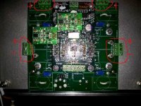
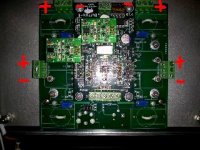
merlin, yeah that set up is pretty much all there is to do, i'm not sure i cant see your pic, but in the orientation you have it, from left to right with the power input at the top goes + |-+|- ________ - |+- | +
dont you still have the psu part lying aroubd? just match it up, but yeah what ive written above is how i have it
Last edited:
of course ive had the top on, for brief spells, but ive been tweaking and playing with stuff and never really bothered to test sink temp after a long spell closed up because it was obviously not a problem. apex jr has some fairly flat finned sinks from active speakers that you could probably put underneath and youll be fine then

yeah easy to do at a glance, because Owen helpfully even marked Gate drain and source. do make sure to use the dacs and therefore the iv boards signal ground as you have marked
you are using lemo single pin coax type for balanced? they make a 2 pin as well, those wont be the best for cmmr, but they sure look cool. what are they connecting to? levinson or something? i'm using lemo in the smaller 2 pin package. how is the voltages looking now; still having problems?
what is the air temp inside, so we have an idea of rise above ambient? sounds like its about the same temp as mine and we will probably end up with about 50c when its all cased up, which is just right for good lifetime of the caps and the dac. that is until we also add other shunt regs into the case 😀
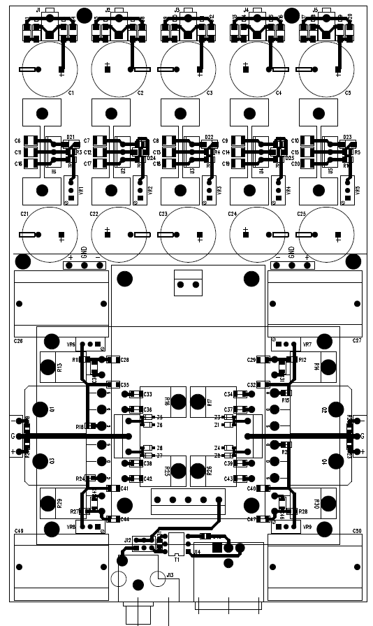
Is there a schematic for the board version merlin el mago is showing? I have seen several so far. I am trying to get caught up on this thread and i think i have missed a large section of it along the way someplace. How did we get from Nelsons original article to this board??
Zc
Zc
you are using lemo single pin coax type for balanced? they make a 2 pin as well, those wont be the best for cmmr, but they sure look cool. what are they connecting to? levinson or something? i'm using lemo in the smaller 2 pin package. how is the voltages looking now; still having problems?
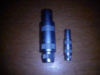
Lemo is FFA 1.S model is twinaxial + ground so perfect for balanced LEMO|FFA.1S.250.CTAC52Z|PLUG, S1, COAX, 50OHM, GROUP1 | Farnell United Kingdom but I bought directly to Lemo, Levinson's use the model FFA 00 see the pic that show the difference between the two models. Voltages are still wrong only decreasing the trimmer can get max 0VDC😕
Attachments
what is the air temp inside, so we have an idea of rise above ambient? sounds like its about the same temp as mine and we will probably end up with about 50c when its all cased up, which is just right for good lifetime of the caps and the dac. that is until we also add other shunt regs into the case 😀
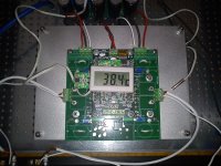
insideyour house i mean, since this is in the open
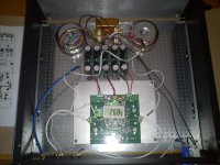
Yes inside house, see pics with ambient temperature 26.8ºC & a general biew of setup, blue cable it's a 75 ohms characteristic impedance: +/- 1 % of the nominal value
Attachments
- Home
- Source & Line
- Digital Line Level
- Build Thread - A New Take on the Classic Pass Labs D1 with an ESS Dac