I'am afraid about high temperature if using Salas Low Voltage Shunt Regulators in the same box.
About voltage any idea how to fix the issue?
About voltage any idea how to fix the issue?
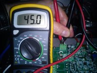
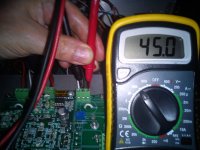
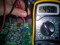
Max voltage Source to Gnd 0.828VDC with trimmer 5K both channels.😡
😡 It's negative voltage so -0.828VDC decreasing the trimmer I get max 0VDC😕
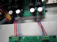
About temperature when IV working the temperature sensor was touching the heatsink & the chassis was always open as shows the pic.
Last edited:
Once this is done, verifiy that the voltage at the drain is about 9 referenced to ground
I measured again:
Right channel
Source to Gnd
Hot +0.001VDC
Cold +0.001VDC
Drain to Gnd
Hot +0.012VDC
Cold +0.012VDC
Left channel
Source to Gnd
Hot -0.004VDC
Cold +0.006VDC
Drain to Gnd
Hot +0.005VDC
Cold +0.005VDC
N.B. increasing ohms with trimmer the voltage between Source & Gnd became negative😕
Please help.
ahh right, the socket just looked different to the lemo i use thats twinax also, i use the FFA.0S size, which is basically exactly the same as yours, but the next size down. they are indeed excellent for balanced audio, better than XLR as the pins are much closer together, so cmmr is better and the impedance is closer to the 110r spec for AES than XLR too, i use the same model in 4 pin for my headphones
yeah thats not enough temp rise i think, doesnt sound like the mosfets are properly on, so the resistors wont be putting out any heat either. so the power supply obviously tests fine when its not connected? its difficult to see in your pictures whats going on and not really all that much to see with smd. something is obviously very wrong, mate, very wrong, are you sure you are hooked up right? hard to know what to tell you with the whole thing basically dead there isnt much clues
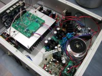
I took some pics of mine as requested, sorry about the delay guys. as you can see its pretty crowded even with the dac platform off, the last pic is my savior, yes its a custom wound potted tx with 10 secondaries from sumR, all at exactly the right voltages and currents for each reg. only the titan board and the D1 will be supplied separately, plus the remote switch on and leds
soon the preregulator board will be done and i'll move to 2 box for the dual dac setup, still not sure what iv i'm going to use for the second dac.
yeah thats not enough temp rise i think, doesnt sound like the mosfets are properly on, so the resistors wont be putting out any heat either. so the power supply obviously tests fine when its not connected? its difficult to see in your pictures whats going on and not really all that much to see with smd. something is obviously very wrong, mate, very wrong, are you sure you are hooked up right? hard to know what to tell you with the whole thing basically dead there isnt much clues
I took some pics of mine as requested, sorry about the delay guys. as you can see its pretty crowded even with the dac platform off, the last pic is my savior, yes its a custom wound potted tx with 10 secondaries from sumR, all at exactly the right voltages and currents for each reg. only the titan board and the D1 will be supplied separately, plus the remote switch on and leds
soon the preregulator board will be done and i'll move to 2 box for the dual dac setup, still not sure what iv i'm going to use for the second dac.
Attachments

Last edited:
of course it can and will be made neater when the transformer leads are trimmed, but because these in there arent permanent i just bundled them up. making up either a sivple pcb, or just perf to mount the caps on more neatly too. i'll eventually get the top on 😀
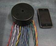
I bought some lemo to use to connect the ackodac to the iv as well, because i have to go through a 5mm acrylic panel, rather than routing through a hole, i decided i'll use a multipin lemo panel mount socket mounted on the floor and then just click the dac in. leads are pretty long at the moment, not the best for performance i'm sure, oh well at least its UPOCC copper 😀
I bought some lemo to use to connect the ackodac to the iv as well, because i have to go through a 5mm acrylic panel, rather than routing through a hole, i decided i'll use a multipin lemo panel mount socket mounted on the floor and then just click the dac in. leads are pretty long at the moment, not the best for performance i'm sure, oh well at least its UPOCC copper 😀
Last edited:
what does it read across the power inputs to ground? you havent got both sides hooked up the same as each other have you? see mine,
looking at it this way
left side + __ GG __ -
right side - __GG __ +
because with all the pins reading nothing, its something either silly, a short, or death
was there any magic smoke?
looking at it this way
left side + __ GG __ -
right side - __GG __ +
because with all the pins reading nothing, its something either silly, a short, or death
was there any magic smoke?
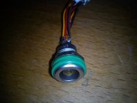
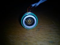
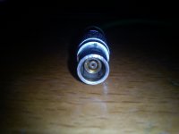
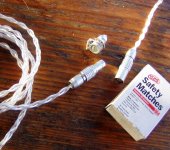
To connect my headphones I use Lemo ERN 1D socket (4 pins + gnd) & Lemo FFA 1D.
The IV will be connected by Lemo to Erno Borbely balanced preamp (not Levinson)😉
Yes at first view I mind your cable are Legenburg?
The IV will be connected by Lemo to Erno Borbely balanced preamp (not Levinson)😉
Yes at first view I mind your cable are Legenburg?
Attachments

Hi Felipe,
Sorry to hear you're having troubles getting the I/V up and running. We'll get to the bottom of it. I've got some questions for you:
1. Did you populate the zener protection diodes where the DAC mates to the I/V PCB? If so, remember that you need to use two in series in opposite directions as there was a mistake on the PCB. Having just the one diode mounted would give you the results you're seeing. If they are, they'll simply shunt the sources to GND making it impossible to get over 0.7V or so at that point. I'd bet that's you're problem. Just remove all the zeners and don't bother with them.
2. Are you using the specified mosfets? If you're using something else, you may need to adjust a few values to get the correct gate volatges.
Let me know and we'll work through the setup to get you up and running
Cheers,
Owen

Hi Felipe,
Sorry to hear you're having troubles getting the I/V up and running. We'll get to the bottom of it. I've got some questions for you:
1. Did you populate the zener protection diodes where the DAC mates to the I/V PCB? If so, remember that you need to use two in series in opposite directions as there was a mistake on the PCB. Having just the one diode mounted would give you the results you're seeing. If they are, they'll simply shunt the sources to GND making it impossible to get over 0.7V or so at that point. I'd bet that's you're problem. Just remove all the zeners and don't bother with them.
2. Are you using the specified mosfets? If you're using something else, you may need to adjust a few values to get the correct gate volatges.
Let me know and we'll work through the setup to get you up and running
Cheers,
Owen
Hi Owen,
Thanks for help.
1.- No I don't connected any zener.
2. I'm using the mosfets you send me with the smd soldered pcb.
Greetings,
Felipe
Hmm... so it's not what I initially thought.
I'm on the road right now so I can't verify the way you have the PSU hooked up, but if you follow the traces as qusp said, it should be easy to verify.
If I were you, I would take the DAC off of there until we get it sorted out. You really don't want to risk damaging the outputs of the ESS DAC if things are hooked up incorrectly somewhere else.
So step 1 would be to remove the DAC and re-measure the voltages at the gate, drain and source of each mosfet to GND. If you can post those up then hopefully we can sort out what's going on.
Regards,
Owen
nice, yeah the lemo gear imo does not have any real competitors if you want compact, real hitech, high quality, no nonsense connectors that also tick all of the audiophile boxes teflon dielectric, copper with gold plate, CNC alloy housings plus quick release. excellent stuff. i dont bother with shield on balanced headphones, so 4 pin is fine. shield just adds capacitive loading. yeah i only mentioned Levinson, as i know he uses lemo on some of his stuff.
hmm your problem is perplexing, you have removed the dac its not connected anymore yes? if not i think you definitely should until you work out the problem.
how about the rest of the board, have you checked voltages elsewhere? just for it to be totally dead like that is strange. youve checked the fuse?
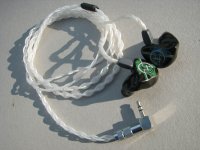
see my jh13 customs below, i have another cable the same, but with the lemo pictured. yes neotech/legenburg 24awg flat copper and the other copper in clear jacket is cryoparts TWCu stranded upocc.
hmm your problem is perplexing, you have removed the dac its not connected anymore yes? if not i think you definitely should until you work out the problem.
how about the rest of the board, have you checked voltages elsewhere? just for it to be totally dead like that is strange. youve checked the fuse?
see my jh13 customs below, i have another cable the same, but with the lemo pictured. yes neotech/legenburg 24awg flat copper and the other copper in clear jacket is cryoparts TWCu stranded upocc.
Attachments
haha opc to the rescue, yeah i just realized he had the dac still on there too and posted urgently to get it the hell off there for the moment.
if the power is as on the previous page it appears to be correct to me.
for anyone else watching, thats probably the most important instruction, do not put the dac on there and connect until you have set the iv up properly and all voltages are correct, then and only then connect it
if the power is as on the previous page it appears to be correct to me.
for anyone else watching, thats probably the most important instruction, do not put the dac on there and connect until you have set the iv up properly and all voltages are correct, then and only then connect it
Felipe,
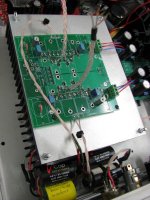
Could you also post a close up picture of just the I/V section without the DAC mounted? It would help if I could take a look at that PCB to verify all the parts are where they need to be.
Cheers,
Owen
Could you also post a close up picture of just the I/V section without the DAC mounted? It would help if I could take a look at that PCB to verify all the parts are where they need to be.
Cheers,
Owen
nice, yeah the lemo gear imo does not have any real competitors if you want compact, real hitech, high quality, no nonsense connectors that also tick all of the audiophile boxes teflon dielectric, copper with gold plate, CNC alloy housings plus quick release. excellent stuff. i dont bother with shield on balanced headphones, so 4 pin is fine. shield just adds capacitive loading. yeah i only mentioned Levinson, as i know he uses lemo on some of his stuff.
hmm your problem is perplexing, you have removed the dac its not connected anymore yes? if not i think you definitely should until you work out the problem.
how about the rest of the board, have you checked voltages elsewhere? just for it to be totally dead like that is strange. youve checked the fuse?
see my jh13 customs below, i have another cable the same, but with the lemo pictured. yes neotech/legenburg 24awg flat copper and the other copper in clear jacket is cryoparts TWCu stranded upocc.
At cryoparts I only bought it's power cable, looks superb the Lemo togheter the TWCu very very cool🙂
hehe thanks, I like it too 😀 sounds good also. I bet its an insane power cable, he makes some pretty over the top stuff. actually the headphone cable above with the lemo is TWSpc basically silver plated TWCu, the TWCu i'm using for the signal wiring in the dac, i often would use silver, but since i'm using VCap CuTF copper/teflon caps, best to stay all copper, owen is shaking his head with pity right now i can feel it.
Felipe,
Could you also post a close up picture of just the I/V section without the DAC mounted? It would help if I could take a look at that PCB to verify all the parts are where they need to be.
Cheers,
Owen
yeah this, though with smd it could be a little tricky, so looking for your mistake huh?? hehe joking mate its odd considering psu voltages are all correct too, psu hookup looks right to me, either shorted wiring somewhere, or the same mistake made on all 4 quadrants of the board. like the wrong part used perhaps would be one option.
dont you think its best he leaves the diodes on there for now? obviously if they are wrong then they need to go, but otherwise till this is done leavem. thats probably what you meant anyway.
hey dont take this the wrong way Felipe, but you definitely put the mica, or keratherm pads under the mosfets on the heatsink? easy to forget, i nearly powered it up before remembering, because you have to put them all on the heatsink to get them all level when you solder them in and then you cant see them to remember to insulate them if you havent already, so easy to miss that.
i cant see if you bolted them from the top, or bolted them down underneath. but then that would probably result in a much more spectacular failure mode than what we see here.
just trying to run through everything i can think of.
anyway i've got to go to bed, hopefully you get it all sorted out without any tears or screaming, it has all the hallmarks of one of those things you cant believe you didnt see before, something really harmless.
anyway good luck!! i'll check in tomorrow to see how you went.
Last edited:
- Home
- Source & Line
- Digital Line Level
- Build Thread - A New Take on the Classic Pass Labs D1 with an ESS Dac