> how does one determine the output power of the Mofo?
Pout = ((VDC*0.64)^2)/RL
("0.64" is 0.707 for peak-to-RMS, and 0.9 for general loss.)
IDC = VDC/RL
(This could perhaps be 0.9VDC but a hair-rich beats any-cold.)
Total DC power = 2.5 times output power
Power making heat in heatsink = also 2.5 times Pout
(Drops to 1.5X when working FULL Sine power, but you only do that on test-bench.)
Thanks for the quick and detailed response. Most of that was beyond my comprehension, so in that I might have to focus on one of the first watt amps.
Is there a thread in the Pass Labs or DIY Audio site that is dedicated to people just starting out in electronics? If not, I think that it could possibly be a good idea.
Thanks again. I do appreciate it.
>> Pout = ((VDC*0.64)^2)/RL
> ....that was beyond my comprehension...
Math.
To estimate power output:
Determine your supply voltage. Call it "VDC".
Multiply VDC by 0.64. (Don't ask why, yet.)
Find the Square of that number. (Multiply it by itself.)
Divide that number by the load resistance "RL".
For 19V supply and 8 Ohm load:
19V times 0.64 makes 12.16.
12.16 times 12.16 makes 148.
148 divided by 8 Ohms makes 18 Watts.
However you want to work through the other calculations. The 19 Volt supply MUST have relatively BIG current; not some old answering-machine wart. The heatsink for a larger MoFo needs to be quite large.
Is the Output power really 18W with a 19Vdc supply ? I thought the designer mentioned 12W.
Mind you, I haven’t measured mine and 12W vs 18W is probably hard to differentiate by ears.
Tomorrow I’m helping a friend building his 2 regular MoFo.
BR
Eric
Mind you, I haven’t measured mine and 12W vs 18W is probably hard to differentiate by ears.
Tomorrow I’m helping a friend building his 2 regular MoFo.
BR
Eric
When I quote power, I'm usually talking about how much you'll get with less than 1 or 2% THD. If you have a look at the THD vs. Power graph from the article, you can see that it makes it to about 18W with around 10% THD. 🙂
I can operate the MoFO with two boards as balance amplifier.
I currently operate the L`Amp 193V and wanted to use of this then the power supply.
If that works I need only a second 193V, another transformer and the other Mofo parts is that correct.
kann ich den MoFO mit zwei Platinen als Balance Verstärker betreiben.
Ich betreibe zur Zeit die L`Amp 193V und wollte von diesem dann das Netzteil nutzen.
Wenn das funktioniert brauche ich nur noch einen zweiten 193V, einen anderen Trafo und die anderen Mofo Teile ist das richtig.
Pass DIY Addict
Joined 2000
Paid Member
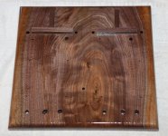
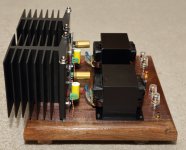
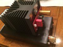
Got my MoFo amp finished over the weekend, though I haven't yet had the opportunity to listen to it.
I made it "bread board" style with short legs and ran all of the wires below deck. I made a small, wooden T-support that goes under the base of the sink to improve the airflow a bit and the last few vanes dangle over the edge of the board.
Since the sinks are isolated from one another, the mosfets are mounted with only thermal paste. This allowed me to bump the bias up to 3A for each channel and still limit thermal rise of the sinks to 25c. Using a Dell power brick rated for 12A delivers 19.1v when both channels are driven. The chokes exhibit a thermal rise of about 9c with 3A of current through them.
Can't wait to hear it tonight! It's rather heavy with all of that metal on top!
Attachments

Last edited:


Pass DIY Addict
Joined 2000
Paid Member
Thanks, guys. I was inspired by the nice work here and some of the breadboard radios from the 1920's

Pass DIY Addict
Joined 2000
Paid Member
Only two albums on the MoFo amp so far (driving it with a BA-3 pre), but there is something special going on here in the midrange. There is a depth to it that when standing in the middle of the room I want to look around to see where sounds are coming from. The M2 seems to have a bit more bass, but there is clearly a depth to the midrange that needs more exploration!
What awesome sound from such a simple circuit!
What awesome sound from such a simple circuit!
My MoFo
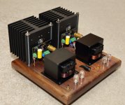
Hi guys
Just wanted to show you some pics of my dual mono MoFo.
Do not hesitate to build this amp, it’s truly amazing. Thanks for sharing your design Michael. Thanks also to Prasi for the pcb.
Both amps were wired on a work bench for a few weeks but I finally decided to give these amps some enclosures. Tomorrow I’ll have to rewire them..
There is a place for a volume in the front but it will be replaced by these circular blue led. (See pics)
Hopefully this will motivate someone to finish their own.
Attachments
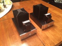

Very nice e_fortier! I'm assuming your SMPS's are in the lower part of the enclosures?
Last edited:
Got my MoFo amp finished over the weekend, though I haven't yet had the opportunity to listen to it.
I made it "bread board" style with short legs and ran all of the wires below deck. I made a small, wooden T-support that goes under the base of the sink to improve the airflow a bit and the last few vanes dangle over the edge of the board.
Since the sinks are isolated from one another, the mosfets are mounted with only thermal paste. This allowed me to bump the bias up to 3A for each channel and still limit thermal rise of the sinks to 25c. Using a Dell power brick rated for 12A delivers 19.1v when both channels are driven. The chokes exhibit a thermal rise of about 9c with 3A of current through them.
Can't wait to hear it tonight! It's rather heavy with all of that metal on top!
Eric,
Nice work as usual.
Cheers,
Greg
Very nice e_forier! I'm assuming your SMPS's are in the lower part of the enclosures?
Thanks.
Yes, the 19vdc smps are inside the enclosure. I’m drawing about 40% of their available power so I’ll see if heat is a concern.
- Home
- Amplifiers
- Pass Labs
- Build This MoFo!