Pass DIY Addict
Joined 2000
Paid Member
I agree with good practice, but this also makes certain assumptions that I cannot always guarantee will always be met as I move things around to play/test/etc or give amps away to friends as gifts. My goal was to find something that prevented me from inadvertently screwing things up.
In some domains, this means not letting me touch things at all 😉.
I'll have to grab a few IEC cords with a switch next time I place an Amazon order!
In some domains, this means not letting me touch things at all 😉.
I'll have to grab a few IEC cords with a switch next time I place an Amazon order!
Pass DIY Addict
Joined 2000
Paid Member
I understand completely - just trying to save my things from myself 😉 It's the computer scientist in me - always trying to keep the dummy user (often me) from doing things to screw it up.
Thank you!
Now I have made some measurements on the choke so I can convert mV to a bias current.
1.0A gives 73 mV
2.0A gives 146 mV
3.0A gives 219 mV
….seems to be consistent…...and shows my choke has RDC = 73 mOhm.
Will be interesting to see if a RDC that low can give a stable bias......if not there is probably a solution for that…...and I have learned something……...again…...
Pass DIY Addict
Joined 2000
Paid Member
MEPER: I suspect you won't run into any specific challenge with maintaining stable bias. I would imagine that a choke that large will also have a pretty serious kickback, far larger than what I am experiencing with my choke. I am curious to see if your larger diode is able to tame the transformer on power down...
We will see…….the problem with stable bias is that my choke has about same RDC as the mosfet and during warm up the mosfet will change its impedance (to smaller value as I understand)…..then current will rise....and more heat is generated….etc....so there could be a "thermal runaway". Think this is the main problem. But that is also part of the fun of DIY to experiment a bit.....
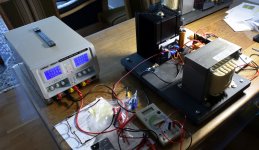
I start testing with a lap supply and using that I slowly turn up and down and I have current limiter activated. The final PSU will be LCLC based so there is a capacitor. I switch off at the AC line level. But it would be nice if the MoFo can handle e.g. if the fuse at the DC level breaks. The idea to have a capacitor on board is not bad...…
I have very little DC across the choke (max. 0.3 V) so maybe the kick back is not that large.....
Pass DIY Addict
Joined 2000
Paid Member
Since much of this is relatively new to me, I'm not sure what to expect for kick back. My guess is that it is directly related to the size of the magnetic field, but I am not sure how much physical size of the choke contributes to this vs the current flow or the voltage potential across the choke... If I had this whole "education thing" to do over again, I think I'd choose EE instead of CompSci 🙂
For comparison, my choke has a DCR of about 0R54, so getting 2.5A bias current means I can measure a 1.35v drop across the choke. With the added cap at DC input, my meter now registers a negative voltage - just briefly - as I pull the plug on the DC power supply. I wasn't able to see this before I added the cap.
For comparison, my choke has a DCR of about 0R54, so getting 2.5A bias current means I can measure a 1.35v drop across the choke. With the added cap at DC input, my meter now registers a negative voltage - just briefly - as I pull the plug on the DC power supply. I wasn't able to see this before I added the cap.
I have learned it many years ago and could probably find the answer in my old books…..
Because my choke is close to be a perfect choke it will probably make a larger kick back....than a choke with some loss in it (large RDC). The formular for the energy stored in a choke can probably be found at the internet....it is probably defined by I and L.
It is important that the choke has a load where it can deliver its energy (speaker in this case......or test load).
Impedance
Great project, even for beginner like me...
But does the MoFo do well with speakers with an impedance around 4 Ohm's?
Great project, even for beginner like me...
But does the MoFo do well with speakers with an impedance around 4 Ohm's?
Pass DIY Addict
Joined 2000
Paid Member
I haven't yet measured mine for frequency response and power output into 4- vs 8-ohms, but I suspect someone around here has already done so.
...The 8 ohms load wasn't suggested for the protection of the MOSFET. IMHO it's just good general practice. 🙂
Yes. Tube-amp abusers learn to always have a load on their lumps if there is any chance of large signals and abrupt cut-off. A Champ that would last decades LOUD and loaded may die in days working without a load (Bachman using Champ as a mere preamp to a big amp for crazy overdrive).
A well-designed (as this is) choke-load amp with nominal load will not kick over 2X the supply. If not loaded, iron-core kicks maybe 10X. 350V Champ kicking to 3500V will eat 1000V insulation; not first-time but little by little. The MoFo topology is less familiar and some consequences are hard to predict. While a possible 200V turn-off kick will not harm the choke insulation, it sneaks to the Gate which is nominal 20V.
Until Murphy's Law is repealed, you should probably:
* Use Zener
* hundreds+ uFd rail cap on board
* "always" have a dummy-load

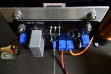
I have started the bias adjustment on my MoFo with the big choke (70 mOhm RDC). Bias seems to be stable after about 1 hour or so. Heatsink reach 46 C with ambient at 23 C.
Now I let it run a hour more or so to check bias stability. After that I will test with a generator to test amp.
My setup may be a little more temperature sensitive than with the original choke.
It is my plan to go to 3A bias. Heatsink should be able to handle that.
Now I let it run a hour more or so to check bias stability. After that I will test with a generator to test amp.
My setup may be a little more temperature sensitive than with the original choke.
It is my plan to go to 3A bias. Heatsink should be able to handle that.
Attachments
Pass DIY Addict
Joined 2000
Paid Member
Great info, as always, PRR! Thank you!
MEPER: Looks like you should have no problem at all with 3A bias on a 20v supply. Your sink is similar in configuration to mine, but a bit taller. I'm seeing max thermal rise of about 27-28c with 19.5v at 2.5A. I haven't yet made a "final" assembly as I am in the middle of experimenting with different thermal interfaces and raw aluminum vs painted surfaces to see what practical thermal differences arise. I might have some data to share in another few days.
MEPER: Looks like you should have no problem at all with 3A bias on a 20v supply. Your sink is similar in configuration to mine, but a bit taller. I'm seeing max thermal rise of about 27-28c with 19.5v at 2.5A. I haven't yet made a "final" assembly as I am in the middle of experimenting with different thermal interfaces and raw aluminum vs painted surfaces to see what practical thermal differences arise. I might have some data to share in another few days.
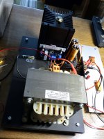
Yes, about 20 kg choke. 12.5 mm2 flat square copper wire used (it should be able to handle 28A). I also installed 2 x 6800 uF big external Jensen audio grade capacitors as output caps.
I tried a switch off and on......and no damage.
When I have tested a bit I will provide some better images.....if it works as expected. To get full voltage swing I need to build the BA-3 pre. Will be next project.
I tried a switch off and on......and no damage.
When I have tested a bit I will provide some better images.....if it works as expected. To get full voltage swing I need to build the BA-3 pre. Will be next project.
Attachments
- Home
- Amplifiers
- Pass Labs
- Build This MoFo!