Pass DIY Addict
Joined 2000
Paid Member
I need to build a "high-low" gain switch to my BA-3 so that I can use it with current amplifiers like the F4 and MoFo (where you need actual gain) and more traditional amps like my M2 and Aleph-J (really just need attenuation). Or maybe build more flexibility into my pre-amp so it can be used as either passive (DCB1 attenuation only) or active (DCB1 fed into BA-3 for gain).
So many projects...
So many projects...
I need to build a "high-low" gain switch to my BA-3 so that I can use it with current amplifiers like the F4 and MoFo (where you need actual gain) and more traditional amps like my M2 and Aleph-J (really just need attenuation). Or maybe build more flexibility into my pre-amp so it can be used as either passive (DCB1 attenuation only) or active (DCB1 fed into BA-3 for gain).
So many projects...
A BA-3 without gain is a BA-1 ?
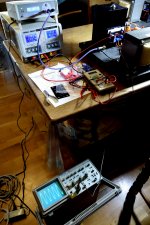
Now I got a signal to the MoFo…..and it seems to work. 250 kHz no problem and 3 Hz works fine also. Sine, triangle, square. So now I just need to modify my PSUs for the ACA so it can handle up to 3A (schottky diodes need heatsink). Also need to adjust and check the other MoFo mono block.
When I put a ear to the choke I can hear the test tone. Putting in a square it gets much louder.
When I put a ear to the choke I can hear the test tone. Putting in a square it gets much louder.
Attachments
The high gain BA3-preamp doesn't push as hard as you'd think. On 90db speakers, I still have to dial the preamp to 3-4 o'clock to get it loud. Not sure you need all the extra non-gain stages. Just a thought.
Pass DIY Addict
Joined 2000
Paid Member

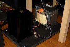
source of choke is in the image 😉
Yes, they are custom made in Denmark.
The original purpose was to get a choke that had so low RDC that output cap could be avoided but that was not possible within reasonable size (next level was 55 kg or so...). I decided to get the big choke anyway to have a lot of iron to have a very linear choke. So it ended up with approx. 73 mOhm and 20 kg. The 3A written on the label is just from my order. It can handle much more if I decide to experiment with high bias current.
I have just tested and verified that with 2.5A bias I have about 0.2V DC. So it would be possible to use it without output cap but I think 0.2V DC is too much. The output cap may also add some safety. These mono blocks are heavy to carry around. They both seems to work as it should using test generator and scope.
Also the 100 mOhm written on it was from my order…..the person who made it wrote a mail that he had found a trick where he could get down to about 70 mOhm…..and this seems to be the case.....
It is this company (the web site has not been updated for a long time...it is a small company):
Galleri | Galleri | Overgaard Transformere
The do a lot of high end audio stuff…..tube output transformers and they told me they make power transformers up to 3.5 kVA for a high end Danish audio company for their big kl A amp. Mechanical damped with rubber and encapsulated in epoxy. It is a 150.000 USD amp.....as I could understand. It probably delivers more than 1 watt in 8 ohm.....and the 1st watt is hopefully good.
Pass DIY Addict
Joined 2000
Paid Member
The company do up to 100 kVA…...that it around 500 kg 🙂
They do transformers for this company:
Danish Audio Design International - Electronics - Malling, Arhus, Denmark - 10 Reviews - 123 Photos | Facebook
The 3.5 kVA trafo may be in the big amp in the picture……..never experienced their system.....
They do transformers for this company:
Danish Audio Design International - Electronics - Malling, Arhus, Denmark - 10 Reviews - 123 Photos | Facebook
The 3.5 kVA trafo may be in the big amp in the picture……..never experienced their system.....
I need to build a "high-low" gain switch to my BA-3 so that I can use it with current amplifiers like the F4 and MoFo (where you need actual gain) and more traditional amps like my M2 and Aleph-J (really just need attenuation). Or maybe build more flexibility into my pre-amp so it can be used as either passive (DCB1 attenuation only) or active (DCB1 fed into BA-3 for gain).
So many projects...
So add another project! If you haven't already, check out the AKSA Lender Preamp by Hugh Dean and XRK971. It can create the voltage swing needed to really power the MoFo. And you can configure it with different daughter boards for different gain levels or even a headphone amp configuration. I have mine running at a more or less standard gain setting right now but I plan to build another set of high gain daughter boards when I get my MoFo up and running.
That's a big choke for sure, but it handle 1.21 jigawatts ?? 😉
Have to watch that movie again
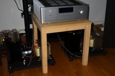
I tested MoFo this night on real speakers (OBL-15).
Modified my ACA LCLC PSUs a bit so Schottky diodes got better cooling. Then went for a bias = 2.5A. Voltage dropped from 24 to 16 volt caused by the internal RDC in the filter chokes. Filter chokes get a little hot but ok. So 16V and 2.5A for the MoFo's. I may change the main transformer later to get higher voltage. MoFo choke stays 100% cool!
It takes 1 hour warm up to everything is stabilized (large heatsinks).
I use my NAD M3 as pre amp (BA3 pre is next project). NAD M3 has a JFET kl. A input stage and it goes to 10 dB in amplification. For 95% of the music I don't need more.
Sound is surprisingly good. Think it has triode like sound in the high and mid tones. Then is has bas control like a solid state. A very good combination. Compared to ACA I find the sound a bit "warmer" and maybe a deeper sound stage. MoFo has more "muscles". I can feel that in the bas section.
Why make power amplifiers so complicated when you only need one transistor?
….and it is 100% silent when in idle…...no "hiss" and no "hum".
I like chokes!
Attachments
Pass DIY Addict
Joined 2000
Paid Member
Congrats on completing your amps! I'm still a little while away from having a pair that are mounted and ready to listen to. A quick jumper across the first L in your LCLC will bring your power supply voltage up a bit, but you'll lose some of your filtering capability. I doubt you'll hear any noise as a result.
Yes, that could be a solution. Then I will have to simulate it first. We will see…..I may order a new set of main transformers.
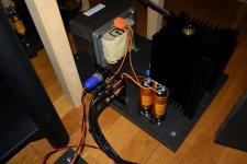
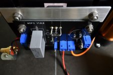
Even that MoFo looks like a very simple build…..it takes some hours. I also went for larger external mounted output caps. The wiring is a bit different. I keep the high current as much as possible away from the PCB. The orange wire is AWG12 to keep the impedance low to the output caps.
Sound is amazing!
Sound is surprisingly good....Why make power amplifiers so complicated when you only need one transistor?
….and it is 100% silent when in idle…...no "hiss" and no "hum".
I like chokes!
Congratulations Meper!
Any fun with the bypass no polarised capacitors for Your output electrochemical's ?
Oh I see nice empty place on the pcb's.
Cheers
 Kudos to the Dude
edit: wait for MuFo MoFo Part II article
Attachments

Congratulations Meper!
Any fun with the bypass no polarised capacitors for Your output electrochemical's ?
Oh I see nice empty place on the pcb's.
Cheers
edit: wait for MuFo MoFo Part II article
Yes, output cap not installed on PCB. It was my intention to use terminals on PCB to connect the external output cap…..but found a better solution for the wiring. The 1k bleeder on PCB is for no use then……
I mounted the RCA connector very close to the input terminals to have very short input signal wires. Think I like that……
I could bypass the output caps if I could live 0.2V DC...….
Attachments
Congratulations.I tested MoFo this night on real speakers (OBL-15).
Modified my ACA LCLC PSUs a bit so Schottky diodes got better cooling. Then went for a bias = 2.5A. Voltage dropped from 24 to 16 volt caused by the internal RDC in the filter chokes. Filter chokes get a little hot but ok. So 16V and 2.5A for the MoFo's. I may change the main transformer later to get higher voltage. MoFo choke stays 100% cool!
It takes 1 hour warm up to everything is stabilized (large heatsinks).
I use my NAD M3 as pre amp (BA3 pre is next project). NAD M3 has a JFET kl. A input stage and it goes to 10 dB in amplification. For 95% of the music I don't need more.
Sound is surprisingly good. Think it has triode like sound in the high and mid tones. Then is has bas control like a solid state. A very good combination. Compared to ACA I find the sound a bit "warmer" and maybe a deeper sound stage. MoFo has more "muscles". I can feel that in the bas section.
Why make power amplifiers so complicated when you only need one transistor?
….and it is 100% silent when in idle…...no "hiss" and no "hum".
I like chokes!
everything you describe fits with the experience I had with the Mofo I built.
- Home
- Amplifiers
- Pass Labs
- Build This MoFo!