Xrk971, that big 10lb coil of #10 wire will have about 4.5 more ohms of dc resistance so your maxium voltage swing would be reduced by about 7.5V . And one thing I would worry about with big air core coils is if you wern't careful there might be some mutual inductance, About the concern about the distortion in these iron core chokes if it indead turns out to be a problem a possible solution was talked about on Tube Cad and even used in this very old OTL. If you look at the circuite a small aircore coil in in seriese with the much larger iron core inductor. Sort of like we use a quality bypass cap across a big electrolitic
Attachments
... rapidely... MoFo meets UMS and spades allowed...
JP
From original MoFo 2 caps to 9 pcs.
Haha 18 caps stereo !!
Only 12 steel spades for two chanels + 2 connection's for free

Cheap gold and diamonds and let's go maximalism.
Simple builds are too easy i guess....what about SMD tiny microscopic thick film resistors
or MP3 players for "Audiophiles" 😀

Attachments

If one replaces the Hammond...As these are power line mains filtering inductors, they may not react as well at higher frequencies.
There's a THD vs. Frequency measurement included in the article. 🙂
Last edited:
Thank you very much for the elect-tech fiction(?)...Beginners...What is "P1 minimum setting"...
Thanks, I think that's a fair point so I cleared it up in the text a little and I'll give it some attention in the video as well.
And, thanks much for the reference to technical articles disguised as stories. I was trying to come up with some examples. 🙂
An amp like that could really tie a system together.
No exotic parts...Dude...this amp demands to be built!
Right on, man

Attachments

Any thoughts on suitable preamps? This looks like a very nice project, especially for first time builders.
A lot of preamps could get the job done. A lot of tube preamps certainly have high output capability. SY's Impasse for sure. I think the good 'ol BOSOZ would swing a lot. It depends on the efficiency of your speakers and the amount of power you want, etc.
A spiffy Pass XP might be fun. 🙂
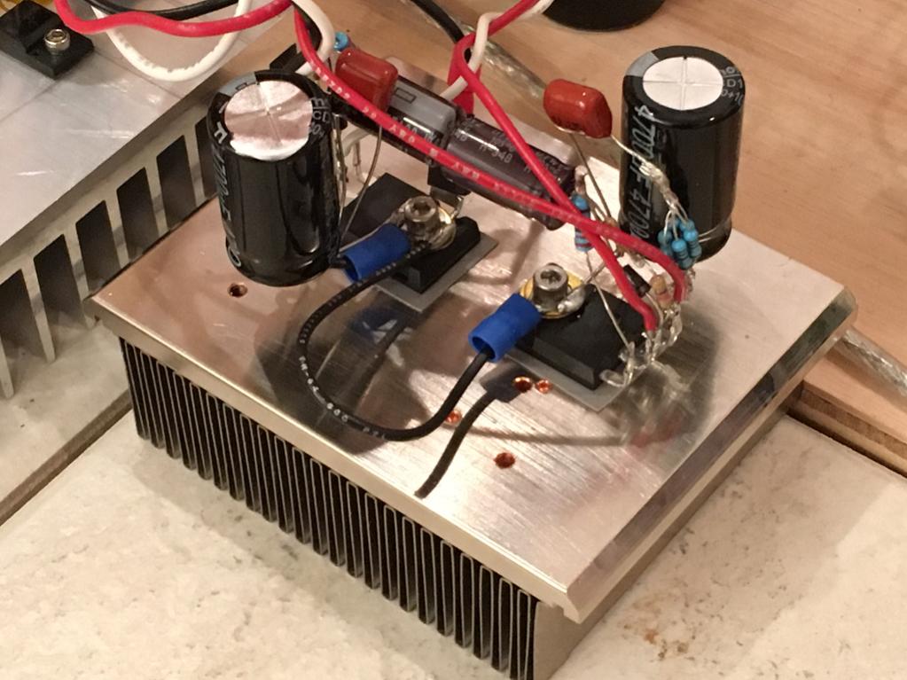
Michael - Where did you get the heat sink extrusions? They're pretty cute. Thanks
Phil
I got those from Newark. 🙂
Am I the only one wondering about the unpopulated zener diode?
I included a spot for an optional 20V Gate protection zener on the PCB to appease the Internet. 🙂
I don't use it.
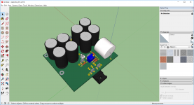
Is now few hours I play music through MOFO...
Wow, that was fast! Well done. Enjoy 🙂
Are there any boards available for this yet?
I'll have some more info on boards very soon. 🙂
@Soundhappy
In the ACA thread, Mr. Pass recommended paralleling of n+1 ELNA Silmic capacitor!
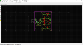
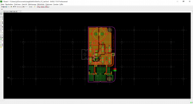
For experimentation, place holder for MKC one (I´ve a big batch Vishay´s 1860 from Pollin).
2mm holes for spade hater.
Vishay/Dale resistors.
Finishing dummy definition for input coupling capacitors to fit different manufacturer ones (Mundorf EVO showned).
Placing done, breadbord for evaluation can be start before finishing PCB.
JP
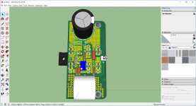
In the ACA thread, Mr. Pass recommended paralleling of n+1 ELNA Silmic capacitor!
For experimentation, place holder for MKC one (I´ve a big batch Vishay´s 1860 from Pollin).
2mm holes for spade hater.
Vishay/Dale resistors.
Finishing dummy definition for input coupling capacitors to fit different manufacturer ones (Mundorf EVO showned).
Placing done, breadbord for evaluation can be start before finishing PCB.
JP
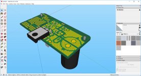
Mr. Rothacher boards existing therefore I´ll never GB my board!
I pick up the design to build one for my own listening pleasure, and yes also for mp3 listening. Just DIY!
Merci/Danke/Thank you Mr. Rothacher
P.S. same procedure and rules for my own Korged B1!
I pick up the design to build one for my own listening pleasure, and yes also for mp3 listening. Just DIY!
Merci/Danke/Thank you Mr. Rothacher
P.S. same procedure and rules for my own Korged B1!
Xrk971, that big 10lb coil of #10 wire will have about 4.5 more ohms of dc resistance so your maxium voltage swing would be reduced by about 7.5V . And one thing I would worry about with big air core coils is if you wern't careful there might be some mutual inductance, About the concern about the distortion in these iron core chokes if it indead turns out to be a problem a possible solution was talked about on Tube Cad and even used in this very old OTL. If you look at the circuite a small aircore coil in in seriese with the much larger iron core inductor. Sort of like we use a quality bypass cap across a big electrolitic
Thanks for the bypass choke tip! Trying to wrap my head around it but now makes perfect sense. The inductance on the big MoFo steel core may drop off at higher frequency. Which is where you want the air core to kick in. Cool!
It's funny but you have basically all the parts that make up a Juma's easy peasy cap multiplier here. 🙂
Here's two of them P2P:
Here's two of them P2P:
The inductance of the big MoFo steel core may drop off at higher frequency.
Not true!
See pdf article page 12
The frequency response is flat with only -2 dB at 200 kHz that is very good wide band 😀
....technical articles disguised as stories. I was trying to come up with some examples. 🙂
Duh!! How could I forget...
John T Frye, Popular Electronics. Carl and Jerry have many electronic adventures. (Frye was an interesting dude too.)
Mac's Radio Service Shop, wise old tech and young kid fixing radios and TVs (and a trip to the hospital when Frye himself had gall-stones). Much Mac can be found on American Radio History.
Barrie Gilbert, guru at the analog.com lanes, wrote several future-fantasies about a Dr Leif in the year 2025, imagining that current-mode design took over the world. Published in Analog Dialog starting around volume 39 number 4.
- Home
- Amplifiers
- Pass Labs
- Build This MoFo!