If you have a dc supply you can push a known current thru and measure the voltage across the coil.
Very good idea! will do that. I have a DC supply with current limiter and A-meter built in. So I can set the current to e.g. 2.5 or 3.0 A and then measure the voltage…….or just read it at the V-meter but probably good make a control measurement with a quality DMM.
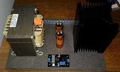
The Jensen caps are 6800 uf / 63 VDC. Have four as I will use two pr. channel in parallel. I picked them up direct at the Jensen factory close to Copenhagen. I was served by the 3. generation of Jensen. They are two 3. generation Jensen brothers which own the factory now. These 6800 uF are not listed at the web. They are not cheap…...approx. 120 USD each incl. 25% Danish tax. I like to use the local suppliers. The chokes were also picked up at the factory.
I can't wait to hear feedback on your monster creation. Good luck!
It will take some time. I also have plans for the Korg preamp and BA3 front end and a couple of 2 x 24 VDC supplies. So I guess some months in the future......but will post how it goes…….when there are some progress…….
If the MoFo was designed with a conventional source resistor and the rail voltage was raised to e.g. 40 VDC how would such an amp perform compared to the current version? …..I know it will be less efficient and burn a lot of power in the source resistor. Does the choke give some "sound qualities" which a conventional design does not...e.g. more "ear friendly" distorsion pattern? ….what about damping factor will that be the same? …..the load has to be seen as parallel to the impedance in the mosfet?
Choke-loaded can give efficiency to 50% in theory. In the form proposed here, over 40% before distortion is audible.
Resistor-loaded is at-BEST 8.5% efficient, and probably under 6% in real life at audible distortion.
Upshot is that you must build 6 times bigger, ENORMOUS dissipation and quite a lump of power.
True, compared to 80 pound iron, the resistor does look an incredible bargain.
See the FAOW plan for resistor-coupled. Scale it from 1+W to 16W, basically 10X power, 10X heatsink, around 3X voltage and current. 57V 6A. I'd have to refine those numbers because the two topologies differ, but 57V 6A and 300W heatsinking does give one pause.
Ok.....so to make it with resistor load is more a theoretical than practical project. The FAOW has very high distortion relative to the bias current which is quite high. I understand how the resistor loaded version works with about half rail voltage at the source of the mosfet and then an absolut need for an output cap. The MoFo was for me so special that it was a "must build" to see for my self how it works. I still does not have the full understanding that you have almost 0V DC at source of the mosfet where you take the output from and only have single rail but the choke gives you the "negative part" of the rail voltage to get double swing.
Do you know if the MoFo clips symmetrical or the negative half clips first?
Do you know if the MoFo clips symmetrical or the negative half clips first?
After simulation in LT Spice i come to the conclusion that the higher the DC resistance of the choke the earlier clips the negative half.
"How can the choke give the negative part of the rail voltage?"
I do not have the proper explanation but i guess the choke behaves somehow like a capacitor. It takes energy to get magnetized and it can release this energy. Exactly what happens in an oscillating LC circuit
The explanation may be wrong but "iron" for sure works, be it as choke loads or in power supplies
Yes, it will store energy and it has to be released in a very controlled way. The mosfet seems to be able to control that. Choke will try to keep current constant and compensate by changing the voltage if current is changed. So from that it is probably obvious that it works. Depending if current is decreased or increased the "kick back" voltage will be either positive or negative......I wonder if it can be explained that simple.
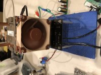
Some pics 🙂
Is it M5 bolts with hex head you use to fasten the MoFo PCB to the heatsink?
Ok......I have ordered some of these. I have same kind of heatsink. I got most components soldered on PCB while watching Tour de France. The acrylic panel to mount connectors may also be my choice. Seems to be 3mm acrylic panels...….they are probably easy to cut.
Attachments
Some pics 🙂
I can see you use an isolator pad between the mosfet and the heatsink. Strictly it is not necessary to electrical isolate the mosfet from the heatsink when you built without a grounded chassis?
So do you use the isolator just instead of thermal grease? ….and not to also electrical isolate the mosfet from the heatsink?
oh yeah
my screwdrivers are especially happy when I tell them that chassis isn't grounded and just heatsink is on full plus potential

my screwdrivers are especially happy when I tell them that chassis isn't grounded and just heatsink is on full plus potential
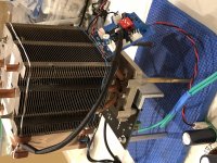
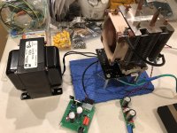
Curiosity got the better of me........
I disassembled a perfectly fine stereo Big MoFo because I had to try the fan/CPU cooler solution that I’ve had good results with in recent builds.
The Big MoFo is another amplifier that can run cpu coolers with very good results! It works so good, I thought the bias was to low because the cooler pipes were barely warm. I checked and It was right at 2.5A. The aluminum angle used to clamp the MOSFET to the copper pad is the hottest part at 42°C. I used a Dell FD841 cooler with a Noctua NF-A8 PWM fan(INCREDIBLY QUIET) and a PWM fan controller sourced from eBay. This cooling system is approximately $25 less than the original 11”x7”x3” aluminum heat sink the MoFo was attached to. And a huge reduction in weight! (This is just one channel)
Attachments


oh yeah
my screwdrivers are especially happy when I tell them that chassis isn't grounded and just heatsink is on full plus potential
Ok..... use of an isolation pad is probably more safe. I was thinking that heat transfer was better just using just thermal grease. I have pads left from the ACA project as I got two stereo kits but built it as mono blocks…...so I will use these. I just discovered that also these mosfets for the MoFo are clever made as screw is electrical isolated so no need for a nylon isolator for the screw.
Nice workCuriosity got the better of me........
I disassembled a perfectly fine stereo Big MoFo because I had to try the fan/CPU cooler solution that I’ve had good results with in recent builds.
The Big MoFo is another amplifier that can run cpu coolers with very good results! It works so good, I thought the bias was to low because the cooler pipes were barely warm. I checked and It was right at 2.5A. The aluminum angle used to clamp the MOSFET to the copper pad is the hottest part at 42°C. I used a Dell FD841 cooler with a Noctua NF-A8 PWM fan(INCREDIBLY QUIET) and a PWM fan controller sourced from eBay. This cooling system is approximately $25 less than the original 11”x7”x3” aluminum heat sink the MoFo was attached to. And a huge reduction in weight! (This is just one channel)

This cooling system is approximately $25 less than the original 11”x7”x3” aluminum heat sink the MoFo was attached to. And a huge reduction in weight! (This is just one channel)
It seems like you could run both channels on the same heat sink, don't you think?
- Home
- Amplifiers
- Pass Labs
- Build This MoFo!