Even with crap phone camera pics???
Danke Zen Mod...
Bitte!
Michael Rothacher
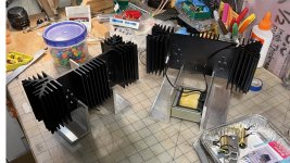
"I will award bonus points if you use oversized heatsinks."
The Dude
'Make chassis the heatsink'
"I will award bonus points if you use oversized heatsinks."
The Dude
'Make chassis the heatsink'

Michael,
Beautiful, elegant, design and even falls into 'Retro' Class.
Who needs tubes???
Beautiful, elegant, design and even falls into 'Retro' Class.
Who needs tubes???
Took a while to read this thread but well worth it. Thanks for all the training!!
Has anyone tried depletion mode mosfets in this CCT? I've seen a few IXYS models that could work for an "auto biased" version if the choke has the right DCR. That would allow us to omit the bias voltage divider and the input cap. I have a few small dual C-core chokes in the 45-60mH range with 1,5-1,9 Ohms DCR that could work for a version biased at somewhere around 1A, should be good for 3-4W @ 8 ohms.

Susan Parker has used IXTH16N10D2 depletion mode 100V Idss=16A (!!!) and Rs(on)=0.1Ω. Hard to find.
- The IXTH6N100D2 you mention has Rs(on)=2.2Ω - I think that is high for a follower.
I'm interested in IXTA6N50D2, depletion mode , Idss=6A, Rs(on)=0.5Ω.
Some time ago I bought several such depletion mode mosfets, they all were fakes, not normally-on.
& With 1,5Ω Rdc it is hard to get 2 amps for single ended. So I am curious too.
The design goal should be - capacitor less. Connect the gate to the input directly. No extra voltage bias.
triode-al: Yeah, now I remember that Susan Parker used tried depletion mode Fets. Must find her thread and read about how it turned out.
Her design is a push-pull MOFO avant la lettre. In fact, it is a design that was common with for instance kilo's of germanium.
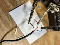
I'm just trying to make a standard MoFo, bought some 65W bricks that are supposed to make 19V at 3.5A but when I take the ends off and test I get NO voltage between Red and Black wires and 3.5VDC between Blue and Red or between Blue and Black. I am confused, any ideas?
Attachments
Pass DIY Addict
Joined 2000
Paid Member
It's a safety feature. No voltage output when not connected to something. Loading it as pinholer indicated will turn on the output.
Last edited:
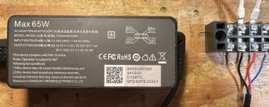
If it's a loading thing, maybe try a lower resistance value. 20V and 6K is about 3.3mA and perhaps the charger thinks whatever is downstream is already charged?
- Home
- Amplifiers
- Pass Labs
- Build This MoFo!