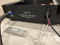
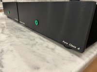
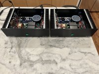
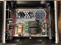
Poseidon’s Voice “MOFO” monoblocks in a 3U/300 enclosure
Ingredients:
Heatsink when fully warmed up is ~ 50 degrees C.
Thanks to:
@Michael Rothacher @6L6 @Nelson Pass @Mark Johnson @prasi @tomchr
Thanks to all the other diyaudio members, you are all an inspiration, always. If anybody wants more pics or clarification, please post.
In the upcoming weeks, I’ll share some subjective commentary.
On to the next project 😉
Best,
Anand.
Ingredients:
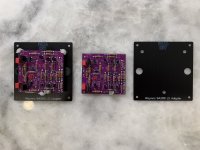
- Neurochrome THAT RX::Mono (discontinued, but Table 14 from this link helps in understanding the circuit)
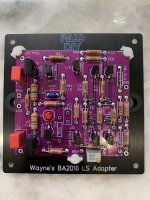
- Wayne Colburn’s excellent linestage/headamp design he revealed at BA2018 and that 6L6 gifted me a while back. Yes, these are the pink boards. They, as you know do not have any mounting holes so lateral thinking had to sink in (thanks Wayne!!). Along came Adafruit’s edge mounting kit and then some prototype sessions on Front Panel Express. I’ve set R17 to 3K (instead of 10K), as such overall gain is ~ 20dB.
- Michael Rothacher’s MOFO using member Prasi’s board layout.
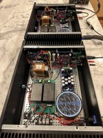
- Lundahl LL2733 dual C-core choke with the chokes wired in parallel such that the DCR is ~ 0.9 ohms.
- Neurochrome Guardian-86 (this is the thru hole version which I soldered years ago, but now discontinued). It is somewhat superfluous in the circuit given that the MOFO is cap coupled on the output. That being said, the 5 second delay at turn on, is a nice feature. And I’m all about safety!
- Neurochrome SMPS-86 (discontinued). This is an excellent switcher supply which includes a soft start and surge protection on the input and a Pi Filter on the output such that the output ripple is << 2.5mV RMS. In my implementation I used two 12V Meanwell Modules and lifted the chassis ground connection, as such it became a +24V supply with 120W capacity for each monoblock. It operates at 50% capacity since I have the MOFO biased at 2.5A. The Meanwell modules in operation are barely warm, about 35 degrees C.
- Mark Johnson’s excellent implementation of a regulated bipolar supply, the VRDN. I have it set at +/- 18V since the THAT RX::Mono is limited to +/- 18V for it’s supply requirements.
Heatsink when fully warmed up is ~ 50 degrees C.
Thanks to:
@Michael Rothacher @6L6 @Nelson Pass @Mark Johnson @prasi @tomchr
Thanks to all the other diyaudio members, you are all an inspiration, always. If anybody wants more pics or clarification, please post.
In the upcoming weeks, I’ll share some subjective commentary.
On to the next project 😉
Best,
Anand.
Attachments
-
 18148782-E6EF-4787-8340-F61E3E315E2B.jpeg359 KB · Views: 630
 -
 77617753-C04B-4BDA-9647-3CA230316413.jpeg526.8 KB · Views: 551
 -
 B72CAF3B-84E2-46F7-B45D-34021758F798.jpeg555.7 KB · Views: 527
 -
 C67B9448-FFF6-4392-81D8-625E6DCF16E7.jpeg514.4 KB · Views: 512
 -
 39212ACA-71F2-451A-B692-530AC3FD936C.jpeg541.7 KB · Views: 474
 -
 A3F146CB-E803-4A7C-958B-C084956BAAFA.jpeg510.1 KB · Views: 530
 -
 960DD788-DF69-41C4-9F0D-D00B0DACD5BC.jpeg364.4 KB · Views: 528
 -
 ED106810-43BC-404A-86CA-9FCAC52B0F6D.jpeg263.3 KB · Views: 593
 -
 1DAB4052-91AF-40E9-8CFD-FC387719B317.jpeg464.6 KB · Views: 651
 -
 380625E3-7226-466B-987E-97BD601A7D68.jpeg594.3 KB · Views: 654
 -
 C3FB1C7C-05D6-4B0D-8F99-2E29898083F3.jpeg439.6 KB · Views: 640
 -
 2DAD64BA-A91F-46D1-841E-D77CC422BCDD.jpeg652.2 KB · Views: 638
Last edited:

Beautiful MoFo Mono's Anand! Top notch craftsmanship
With the BA2018 frontend, no worries about using a preamp with cojones.

With the BA2018 frontend, no worries about using a preamp with cojones.
Had a Great visit with @poseidonsvoice and got to see the Mofo in person. @poseidonsvoice bailed me out when I screwed up my F6 and got it working and biased. It is shown in the picture and the rest of the system is a Tekton Mini Lore in a small room. The Mofo was amazing. Not sure of the adjective but more presence and clarity. than my F6's. Plus the Mofos are gorgeous really quality work

Henry,
I’m not Vunce, but with Wayne’s BA2018 linestage, gain is set by the ratio of feedback resistors, R16 and R17.
For example, R16 is 27K ohms. I would leave that alone, and not change it. R17 you can change and it is 10K ohms stock.
As such, the gain (Av) = R16/R17 +1 = 3.7 times.
3.7X when used in the dB gain equation (gain = 20* log [Vf/Vi] ) is
20* log 3.7 = 11dB.
In my implementation, I changed R17 to 3K ohms, so Av=10 which is 20dB gain.
If you want 26dB gain, then change R17 to 1.5K ohms and keep R16 at 27K ohms.
Hope this helps.
Best,
Anand.
thank you very much Anand. I assume that 20db is more than enough for my purpose 🙂 Any comments about choosing the BA2018 as a pre in favour of other options for the Mofo - well your report some posts above speaks for itself 🙂
When I built the MoFo I also built BA3-pre to drive it. BA3-pre has high voltage swing. I found out later that a pre-amp like Korg-B1 was more than enough for my 94 dB speakers. Good to know the sensitivity of the speakers. It is an advantage to have as little voltage gain in the system as possible to keep noise level down.
Once some Avantgarde Acoustic horn speakers was demoed for me. I think the sensitivity was about 107 dB or so.
In listening position (4m or so from center of speakers) the "hiss" sound from the amps was very audible (in idle without music). This was a very bad experience.
I don't hear any "hiss" unless I put my ear 10 cm to tweeter or so. That is how I think it should be 🙂
Apart from that BA3-pre is a very nice amp for MoFo.......no hiss.......from my speakers.
You probably don't need a pre that can drive MoFo into clipping.......is my guess.
Yes, schoolboy error!Load R5 should be 8 Ohms?
I've worked out how to do a DC op point and set the divider for c1.7A across the choke. I think. It wasn't too far from the mid point of the divider.The rest is "practical shortcuts".
What current is the MOSFET running at? 1mA or 100A is unrealistic. That's the first place I would throw a (virtual)meter.
SortedR1 is to avoid plug-in pops, skip it for preliminary eval.
R7 R4 can be combined (you are correct that you do not need filtering or trimmers here).
R2 can be omitted because SPICE does not know about wiring resonances (unless you laboriously set it up).
I gave the choke a series resistance of 0.8R to represent the DCR I measured.The graph going down to -55mdB is meaningless: -0.055dB is real-real tiny.
I do not know why "stepped choke" seems to flatten out at -1.8dB. I don't see any step-network? I may be confused by monster cap driving 1k resistor. Or does your choke have internal resistance (if so: a proper amount)?
Investigating a little more, running the sim from 1Hz rather than 10Hz gave this plot, which explains the previous sim, but doesn't really make sense to me.
So I'm still suspecting my Spice skills need work. I've uploaded the Spice .asc in case anyone's interested enough to have a play. And can perhaps tell me what I'm doing wrong.
Attachments
Very nice looking build Anand! I have to admit many of the technical aspects are over my head. However, I'm learning a great deal as I go.
I noticed you incorporated the BA2018 as a preamp. I may well be looking for a preamp project down the road if my current build works out. Thanks for sharing this project with all of us!
I noticed you incorporated the BA2018 as a preamp. I may well be looking for a preamp project down the road if my current build works out. Thanks for sharing this project with all of us!
I just found I have 16x Exicon 08N16 Mosfets. This looks like an early version of the 10N20 with 160V max.
Could this be used in the MoFo? Would any changes be necessary? Grateful for any help here.
I can't find any data on this unit, closest is 10N16


Could this be used in the MoFo? Would any changes be necessary? Grateful for any help here.
I can't find any data on this unit, closest is 10N16
They can be used with no changes at all. As ECX10N16 has lower transconductance than IRF250, amplifier output impedance will be higher, probably ≥ 0.5 Ω.
However, that laterals have 5 times less input capacitance, so it will be easy to drive it with tube preamplifier.
However, that laterals have 5 times less input capacitance, so it will be easy to drive it with tube preamplifier.
Thanks for your reply! The schematic I have is attached. Is this OK?

Andy,
You should be fine. Just remember that with Lateral Mosfets, pin 1 is the Gate, pin 2 is the Source and pin 3 is the Drain. Vertical Mosfets like the IRF250 have different pin designations (Pin 1 = Gate, Pin 2 = Drain, Pin 3= Source) and if your pcb was designed for Vertical Mosfets, you'll have to do some cross wiring.
Please let us know of your results!
I've thought about using N channel SemiSouth JFETS myself, but too many projects and too little time!!
Best,
Anand.
Last edited:
Here's my proposed heatsinks. I have 4 of these square ones. Each is 4.5" x 4.5" x 5" or 11x11x12.5cm high. Weight is 1.3kg.
I could use one for each Exicicon 8N16, total two. Or I could bolt a couple together, one pair on each side, to make a square enclosure with all four.
If I bolt two of these together, can I mount the Mosfet on the middle part sticking out, where the two pieces will be bolted together?

I could use one for each Exicicon 8N16, total two. Or I could bolt a couple together, one pair on each side, to make a square enclosure with all four.
If I bolt two of these together, can I mount the Mosfet on the middle part sticking out, where the two pieces will be bolted together?
One MOSFET per heatsink would be best, mounted 1/3 up from the bottom.
- Home
- Amplifiers
- Pass Labs
- Build This MoFo!