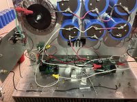
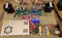
couldn't resist to build the 'MEGA MOFO'. 200mH choke, 195T10 as the L in CLC. 37VDS@3A...for now. I have a BOZ to drive it. I built a J113 buffer following Ben Mah's schematic for his SIT explorations. Will the buffer be a benefit between the BOZ and MOFO? Just fired it up, letting it settle, havent connected anything in the inputs yet.
Attachments
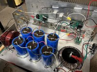

Well, that is Mega!
As for the J113 buffer, I don't think it is able to swing the voltage to feed a high power follower unless the J113 is cascoded. It will work with a voltage gain amp though.
For a simple buffer that can swing voltage, a DN2540 is a better candidate. That is what I used in my 2SK79 preamp.
As for the J113 buffer, I don't think it is able to swing the voltage to feed a high power follower unless the J113 is cascoded. It will work with a voltage gain amp though.
For a simple buffer that can swing voltage, a DN2540 is a better candidate. That is what I used in my 2SK79 preamp.
Last edited:
Has something happened to the build this story on the first link went to open it and the link seems broken is it still available?
https://6moons.com/audioreviews2/mofo/mofo.pdfHas something happened to the build this story on the first link went to open it and the link seems broken is it still available?
Best,
Anand.
Thanks 👍
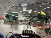
After the mega posted above, here is a mini, powered for now by an IRFP610 and a Hammond 159ZC

This is going to be a guitar amp, powering a 98dB Celestion Greenback at home-friendly volumes
I tested it at ACA mini specs (24V @0.4A) and at 21V, and it is already much more powerful than I need. The main issue at this point is heat, since the aluminum is flimsy, and I want to avoid extra heatsinks.
What remains now is tests with voltages and biasing to see how it sounds and how it clips at various points. I got a Meanwell LRS-75-24 to use with it, but I think I will go with a transformer and filters instead.
I am in the process of wrapping up the AMB Alpha 20 preamp for the Mofo (& First Watt F4). I was thinking about setting the voltage gain around 8 (for 18db). I could go as high as 20 (26db) with the resistor values I have on hand. Do you see any reason to go that high?
Much appreciated.
Much appreciated.
your speaks in your room with your ears
all that deciding how much Volts you need to push through speakers
all that deciding how much Volts you need to push through speakers
Ooh, I'm very interested in that , @dimkasta .After the mega posted above, here is a mini, powered for now by an IRFP610 and a Hammond 159ZC
...
This is going to be a guitar amp, powering a 98dB Celestion Greenback at home-friendly volumes
I built a tube amp (kit) for my son, and then wondered if a MoFo would make a more portable alternative.
Kind regards,
Drew
I'm a little late to this party, I've had the parts for two or three years but life got in the way. But here's my cheapo build.
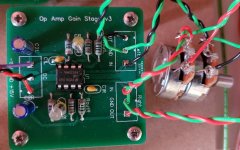
I gave up on SS a long time ago but the MoFo has surprised me 🙂. My SET-friendly speakers don't need a lot of gain and for a while I ran the MoFo without any pre amp but I built a simple op amp gain stage and 5x gives about as much gain as the 45 SET I'm currently using. The sound is remarkably close but the 45 amp has a lot of expensive parts...
My speakers are active and I'm considering building more MoFo and I have a question about the size of the output cap C2.
If I understand correctly the two equations needed are:
XL = 2.pi.f.H
XC = 1/2.pi.f.C
Considering the stock 193T choke (50mH) and 6800uF cap and assuming speaker reactance of 8R:
choke: f = 8 / 2 x pi x 0.050 = 25.5Hz
cap: f = 1 / 2 x pi x 0.0068 x 8 = 2.9Hz
Why is the cap so much larger than needed when a 800uF cap would give f = 25Hz? Is it to avoid doubling of poles at the same frequency? What am I missing/misunderstanding/doing wrong?
Attachments
Hi, simon2a3. Try to understand this: XL is in parallel with load and XC is in series! Make a simple design with these 3 components and you will have the answer.
Last edited:
Hi gheo23, thanks for the hints. I've done some reading but can't make sense of this, can you explain some more?
Look, assuming C=800uF and XC=10ohms( in fact 9.95) at 20hz and load 8ohms let's see what is the voltage on load.
For ease calculation let be the voltage output 18V. So, total drop on XC will be 10volts and on load 8volts! On load
will have less than 1/2 of output , 40% in fact. Onother reason for looses is to minimize inductance of coil wich divide
the total amount of current thru load, the power on load decreasing.
Thanks again gheo23, I appreciate your help.
Okay, I can see that with a cap of 800uF 44% of the voltage is across the load, and with a 6800uF cap there would be 87% I think.
Looking at the inductor I think there would be 56% across the load as it's in parallel with the inductor.
I can't make the link with how to size the cap and choke though.
No. The choke works against the Source impedance of the MOSFET, which may be <1 Ohm. (In parallel with the 8r, so still <1r.)choke: f = 8 / 2 x pi x 0.050 = 25.5Hz
So the choke corner is below 2.6Hz, which is low enough for jazz. Even most pipe-organ. (Actually the last pipes I micced were next to a truck highway and I had to low-cut the deep-deep rumble.)
Also, in classical design 1960-2010, a Hz of aluminum (cap) is a lot cheaper than a Hz of iron (choke). So it would make sense to make the iron barely big enough and over-over-size the cap. (This also lowers cap THD, though oversize iron also lowers THD.)
In this case we have an oddly cheap lump of iron (kitchen appliance byproducts), and we accept what we get. Despite people figuring "8" it actually works much better than that.
(And I am sure none of my recordings have useful <25Hz in the grooves or bits, though I have heard of people who do.)
The easy way is to simulate the output circuit ( Mutisim, or others ) and the other way is maths ! A pen, a sheet and...sweat.I can't make the link with how to size the cap and choke though.
No. The choke works against the Source impedance of the MOSFET, which may be <1 Ohm. (In parallel with the 8r, so still <1r.)
So the choke corner is below 2.6Hz, which is low enough for jazz.
Right I see, I think. So if for instance I wanted to make an amp for a supertweeter that rolled off below 5kHz, assuming an XL of 1R the choke would need to be bigger than 32microhenries? Which seems very small but means I could use an affordable air cored choke with baked varnish, like this
https://www.hificollective.co.uk/catalog/mundorf-ll45-0-1-mh-inductor.html
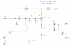
Curiosity got the better of me and I thought I'd try to learn some Spice and model it. This is with a 50mH choke:

This is with a stepped choke of 1mH to 21mH in 2mH steps:

I'm not sure I fully trust my Spice "skills" though...
This is with a stepped choke of 1mH to 21mH in 2mH steps:
I'm not sure I fully trust my Spice "skills" though...
Load R5 should be 8 Ohms?Spice "skills"
The rest is "practical shortcuts".
What current is the MOSFET running at? 1mA or 100A is unrealistic. That's the first place I would throw a (virtual)meter.
R1 is to avoid plug-in pops, skip it for preliminary eval.
R7 R4 can be combined (you are correct that you do not need filtering or trimmers here).
R2 can be omitted because SPICE does not know about wiring resonances (unless you laboriously set it up).
The graph going down to -55mdB is meaningless: -0.055dB is real-real tiny.
I do not know why "stepped choke" seems to flatten out at -1.8dB. I don't see any step-network? I may be confused by monster cap driving 1k resistor. Or does your choke have internal resistance (if so: a proper amount)?
- Home
- Amplifiers
- Pass Labs
- Build This MoFo!