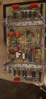
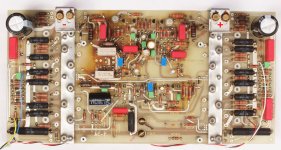
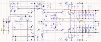
In the third picture you can see the capacitor which i mension in my previous post.
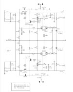
This is one channel only. There are a lot of components wich are missing in the schematics. Does someone can help?
This is one channel only. There are a lot of components wich are missing in the schematics. Does someone can help?
Attachments

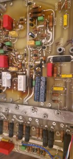
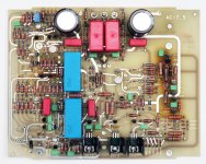

Hi Hans, Thank you for the images. I tried to find out where in the schematic is this electrolyte capacitor 470uF 100V.
Do you know where is it (the black one in the "frontside" image) in the circuit ?
Do you know where is it (the black one in the "frontside" image) in the circuit ?
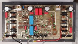
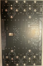
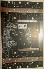
Hi, again. I decided to create a new board because the old boards look like a crap. The new board fits perfectly to the current heatsink and uses the same power transistors and drivers.
The topology of the scheme is almost the same but there are improvements when the amplifier is clipping and better voltage regulators. Current limiter is integrated to the new board as well.
The boards arrived yesterday therefore i will test them soon and I hope everything is fine.
Here are some photos of the new boards.
Attachments

Hello whitesnake,
Lots of respect what you have done and I wish a lot of luck that the new boards are working.
Lots of respect what you have done and I wish a lot of luck that the new boards are working.
Thank you, the board has some small issues but nothing crucial, so it is fine. I ran the board and did some tests. It looks ok. There is no oscillations. I need to choose some values of some components for best performance and test with all power transistors, because now I tested only with 4. Here is one photo of the progress.
Attachments
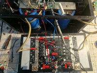
I used some parts from my old boards and when I unsolder the components i found out there is many cracked capacitors probably because of the heat. The old board uses very high current for VAS because of the used transistors and there are many resistors which make a lot of heat. Here there is not issues with the heat. So I suggest the owners to check.
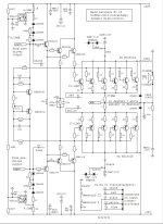
Here is the my circuit.
Here is the my circuit.
Attachments

I think the 23 is better than the 23.5 because the 23.5 has two boards (higher parasitic capacitance), uses discrete oamp for the inverting input of the final stage(more complexity), while the 23 has a simple buffer, which is enough for me. In the new board, the input resistance of the inverting input is 17k ohm, which is quite enough for any preamp, if not it can be easily changed.Can your board be used to upgrade ML No. 23 to 23.5?
If your amplifier works, don't touch it, you can just check for the capacitors I described.
If anyone wants to play I can provide boards.
My is ML23.5 i think but this doesn't matter because there is no mechanical difference between them only in schematic and this additional board for input part of the circuit.
Last edited:
I missed your schematic in #50, now I can see what you did.
Quite some differences are noticeable, espcially the Fet input.
Succes with your design.
Hans
Quite some differences are noticeable, espcially the Fet input.
Succes with your design.
Hans
I have a ML23 and you can find a long topic from the repairing process here. Unfortunately, the right channel is again broken. This would be a good moment to try your boards, whitesnake. I have also a few old original boards with most of the components in place so building one or two new boards should be quite straightforward process.
Is the new board fully functional?
Is the new board fully functional?
I think one of the output transistors are again shorted somehow but hard to find which one... especially the ones that are routed bottom side of the pcb are now hard to solder because it requires a lot of heat. The board has seen its best days...
Can you discribe how exactly happened? Is it hotter then usually? Is it happening when you turn it on or you are sounding very loud?
Last edited:
One day I just turned it on and I heard just hum from transformer and no sound in the right channel. I connected two 60w lamps in the positive and negative vcc unreg rails. There is about 85V drop in the lamps even if I turn the biasing pot completely open. That means something is wrong in the output stage. Everything works until he R50 in the schematic.
- Home
- Amplifiers
- Solid State
- Build the Mark Levinson 23.5 from schematic?