I think that's a good decision.27.5 is fine by me, I do not need that much wattage🙂
In case you don't have the full documentation, here it is.
Hans
Attachments
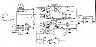
I have just found this picture, it looks like it matches picture 2 in post 3
It says AC-8 Audio channel current gain used in 27.5, so it is exactly as you say, a schematic of the 27.5 🙂

It says AC-8 Audio channel current gain used in 27.5, so it is exactly as you say, a schematic of the 27.5 🙂
I think that's a good decision.
In case you don't have the full documentation, here it is.
Hans
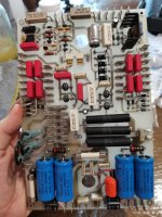
I can see what looks like two PCB boards that looks like they are repeated twice but with different numbers. Is there a difference or why both board repeated twice?
What does these two symbols mean?
Same designation as normal diodes (CR)

Capacitor designation and properly polarized.

Same designation as normal diodes (CR)
Capacitor designation and properly polarized.
Looking at the circuit, what do you think the function could be. When understanding their function, the solution is easily found.
Hans
Hans
What do you mean with "working on".I'm working on a 23.5 now and welcome any documentation the group can post here... thanks!
Are you repairing one ?
Hans
He should have googled and learned from it himself.Please, have a look in the attached datasheet.
It's obvious that a current limit is needed between zener and diode.
When we give him all the answers, we are building an amp for him and he still doesn't understand what het did.
Hans
Yes.What do you mean with "working on".
Are you repairing one ?
Hans
Dear Hans, I do 100% understand your comment and would normally say that you are right. 🙂He should have googled and learned from it himself.
It's obvious that a current limit is needed between zener and diode.
When we give him all the answers, we are building an amp for him and he still doesn't understand what het did.
Hans
I have to say that I did try to search for CR160 and a lot of other things, about 98% of what I have done until now is found out in that way. When I did search after CR160, did I get thousands and thousands of results, and by refining the search, did I still end up with about 25 different types of components, 10 of them could I easily ignore.
I am a beginner out in this fantastic hobby and spend hours and hours on reading, watching videos and trying to find things out. Unfortunately, do I stumble upon things I do not have enough knowledge to solve by myself, and I try to ask you.
Please believe me when I say that your help is very much appreciated and helps me over "bumps" I can't get over by myself, but before asking you have I maybe spend a week trying to solve the problem myself. 🙂
May I please ask why a current limiting diode is used between a zener and a diode? I did think that they had about the same "one way" function and one of them would be enough, unless you need some voltage drop?
The reason I’m giving comment is to trying to make you aware that you have a long way to go.Dear Hans, I do 100% understand your comment and would normally say that you are right. 🙂
I have to say that I did try to search for CR160 and a lot of other things, about 98% of what I have done until now is found out in that way. When I did search after CR160, did I get thousands and thousands of results, and by refining the search, did I still end up with about 25 different types of components, 10 of them could I easily ignore.
I am a beginner out in this fantastic hobby and spend hours and hours on reading, watching videos and trying to find things out. Unfortunately, do I stumble upon things I do not have enough knowledge to solve by myself, and I try to ask you.
Please believe me when I say that your help is very much appreciated and helps me over "bumps" I can't get over by myself, but before asking you have I maybe spend a week trying to solve the problem myself. 🙂
May I please ask why a current limiting diode is used between a zener and a diode? I did think that they had about the same "one way" function and one of them would be enough, unless you need some voltage drop?
Building such a complex amp as a novice is like wanting to step in a F1 car with no driving experience.
It may look easy, like pushing the throttle and just turning the steering wheel, but you will not even get the thing in motion and if so, you will most likely crash.
My advise would be to start with a simpler and well documented amp, like there are many on this forum. That will help you to climb the very rewarding ladder of making your own gear.
To answer you question concerning the zener.
A zener is a voltage limiter that starts conducting once the specified voltage is reached.
But as from this point, because it will try to keep the voltage fixed, current is undefined and the thing will blow itself. But with a simple resistor you can limit the zener current. Even more so, when using a current limiter instead of a resistor will result in a very stable voltage on the zener independent of the value of the voltage source.
Hans
Hans, you are 100% right in what you are saying about a novice trying to design a rocket to Mars, but my idea is maybe sane or more insane, dependent on how you are looking at the things. 🙂
What I am doing is to use a schematic and documentation with nearly everything on it, meaning that I am not so much designing nor understanding the entire circuit, but I am instead trying to copy the things, learn how to redraw a schematic, find exact components, learn about drawing the PCB and so on, this is in a way my try to learn the more basic part of the electronic.
If it gives sound, then great, if not, then do I now have to see where I made a mistake on something that is known to work from the producer.
My goal is not so much to build an amplifier but more trying to learn all the "easy" tasks that goes into finding components, making sure my schematic is correct and so on.
Thanks for your Zener explanation! I have seen the Zener used in reverse from negative to positive to set the voltage on a exact level, I have never seen a Zener been followed by a resistor to control voltage... does that not give a short if the Zener is just placed on the main leads if voltage goes above the Zeners max voltage?
I have thought that if you placed a Zenor would that decide the voltage and as you say let the current go through as it wanted, but if you then placed a current limiter, would the current set max current while voltage got to run amok. <meaning that to combine both would be two functions, fighting each other, just as if you placed a conductor and a capacitor in series, would block both AC and DC.
By the way, it looks to me as if they have not a schematic for the last PCB in the documentation?
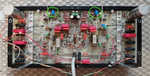
The schematic and the PCB that are in the documentation belong together and are correct.
Here you have some pictures.
Hans
Btw, a conductor in series with a cap would only block DC and not AC.
Here you have some pictures.
Hans
Btw, a conductor in series with a cap would only block DC and not AC.
Attachments
You are simply great!!! And all these are from the 27.5?
Yes sorry I meant an inductor in series with a capacitor🙂
Yes sorry I meant an inductor in series with a capacitor🙂
Can anyone help me find the last iteration of the 22.5 dull schematic, nit this bastardized 27.5 chimera?
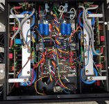
Hello everyone! I have a Mark Levinson 23.5 amp that doesn't work at all. Both channels are broken and I'm trying to get them back but someone before me tried to fix it with no luck and there are some missing parts and mods. I checked some circuits from internet but they are different to some extent.
I was looking at some pictures of the inside and realized that there are different versions of the board.
My version has two boards per channel and on the one of it(the botton with power transistors) there is an electrolit capacitor 470uF/100V with diode and resistor which are connected to the top board. Is this an original? I will add some photos.
Does someone already have the full schematics of the amp?
- Home
- Amplifiers
- Solid State
- Build the Mark Levinson 23.5 from schematic?