I managed to get 250 WPC out of that board and over 500 watts with both channels paralleled. The stories are somewhere in that long thread. I used 35LR6 tubes to get there, so try searching the above linked thread for that number. That was done as a "squeeze it for all it's got" kind of experiment and was done using outboard bench power supplies.They are most likely buried in Pete's original thread here: https://www.diyaudio.com/community/threads/posted-new-p-p-power-amp-design.151206/
George aka @Tubelab_com might be able to pinpoint some specific examples. He has built a few high powered amps.
jeff
Somewhere later in the thread I built a 125 WPC version that used two power transformers with very few modifications to the board. That amp used 6HJ5 tubes, and several clones of that design were built.

Will the board take 450 volts with uprated caps?Somewhere later in the thread I built a 125 WPC version that used two power transformers with very few modifications to the board.
jeff
I'm in the process of building a higher powered version based on these links:
Michelag January 20 2021
Michelag June 2 2021
tubelab_com July 23 2020
Michelag January 20 2021
Michelag June 2 2021
tubelab_com July 23 2020
My first round of adventures with this board involved higher voltage caps and more transformer voltage to the board. This is fine for mild power boosts. At some power level the typical 1N4007 1 amp 1000 volt diode will blow, so I rigged in some bigger 3 amp diodes. You may also need to upgrade the heat sinks on the mosfets in the power supply.Will the board take 450 volts with uprated caps?
jeff
Then I found the better way. Build the board as intended with 450 or 500 volt caps, run it on a transformer that puts the B+ in the 300 to 400 volt volt range and add a second power supply that only feeds the output tube plates. This positive side of this supply only goes to the CT on the OPT primaries, and does not connect to the board at all, so no board mods are needed.
There are two ways to do this, and I have used both. The output tube plate supply can be in the 500 to 650 volt range and connected between board ground and the OPT CT to supply only the output tube plates. It will need to supply all of the energy consumed by the output tube plates.
It is also possible to build a 200 to 300 volt supply that's capable of supplying the current needed by the tube plates and stacking it on top of the power supply that is already used to feed the board. I used an Antek toroid, 4 X 3 amp diodes and a big 450 volt cap for my "boost" supply. This would also require upgrading the board's own supply to handle the additional current demands. You would connect the negative side of the external supply to the positive end of C8 (before the regulator). Diodes D1 and D2 need to be upgraded to 3 amp diodes.
This is almost exactly how I have it here. The differences are a higher current regulator, C8 is bigger, off the board, and bypassed with two motor run caps in parallel. D1 and D2 are 3 amp diodes, but I added two more for a full bridge. Using two identical Antek toroids. The second “boost supply” has a full bridge soldered to a couple large electrolytics also with two motor run caps in parallel.I used an Antek toroid, 4 X 3 amp diodes and a big 450 volt cap for my "boost" supply. This would also require upgrading the board's own supply to handle the additional current demands. You would connect the negative side of the external supply to the positive end of C8 (before the regulator). Diodes D1 and D2 need to be upgraded to 3 amp diodes.
Need some help here.
6LW6 tubes, all NOS.
630V to the plates
140V to screens
6.4V heater voltage measured at the tube
I have to adjust the bias to near 0V before I see any current through the tubes. I figured I’d need a lot of bias, so it’s an 80v supply, and worked fine with 6HJ5 tubes.
Really not understanding what I could be missing here. I can only get one tube per side to conduct at all by turning the bias all the way (up?) and turning the balance pot all the way to one tube.
Last edited:
Is it possible they have a "secret" internal connection like the 35LR6 tubes that George mentioned? Just throwing that out there. 🙂6LW6 tubes, all NOS.
@Tubelab_com Thanks for the info.
jeff
I thought about something like that. I only ran 3 wires to the tube sockets, plus the plate wire and the two heater wires; pins 2, 3, 5.

I’ll have to check I didn’t get the screen on the wrong pin or something.
I’ll have to check I didn’t get the screen on the wrong pin or something.
It does smell like an open screen. Uh, oh. Where did all my gain go and why is there a ton of crossover distortion? Check the screen supply fuse - yup, there it is.
The pin 7 thing is documented on the 6LR6 / 35LR6 data sheet as an internal connection (do not use) pin. I have ignored these warnings in the past if I didn't actually see anything connected to the affected pin. In this case SOME 35LR6 tubes (Sylvania I think) do have a connection from pin 7 to the mid tap on the heater. The toasty looking used GE 6LR6's that I had previously tested the amp with had nothing connected to pin 7, so I was quite surprised by the exploding cap until I measured B+ on the heater circuit.Is it possible they have a "secret" internal connection like the 35LR6 tubes that George mentioned? Just throwing that out there. 🙂
I have seen several different sets of internal guts and two different bulb sizes on the 6LW6 tubes that I have. Pin 6 is connected to the cathode on a Sylvania 6LW6 that I have laying around. It could be connected to something else, or not to anything on another tube. It wouldn't surprise me to find pin 4 connected to an element inside the tube on some tubes, though it goes to nothing in this tube.
In another unfortunate experience, I learned that having the plate supply voltage go away while the screens are powered will instantly vaporize the screen grids as they will try to eat all the plate current. I saw two new Electro Harmonix KT88 flash like old school photographic flash bulbs when I accidentally pulled the banana plug for the plate voltage out of the power supply. They draw very little current at zero bias now.
I managed to get out to the shop for a few minutes and check the wiring, and the socket wiring is all correct. I doubt I have 4 bad tubes, but I guess that’s possible. Nothing has smelled bad or made any noises other than the screen mosfet when I first shorted that, but I didn’t have tubes in at that time.
I may try some more tubes, as I bought 10 of them, but I’m doubtful this is the solution.
I may try some more tubes, as I bought 10 of them, but I’m doubtful this is the solution.
Resistor in the drain of the mosfet - cause it to drop out of regulation if screen current peaks too high. Saves the mosfet too, providing you properly clamp the gate.
I think I figured out the problem. All voltages were checking out fine, nothing fried. Couldn’t be all four tubes I put in were duds. Had to double check what I was actually double checking; has to be something with the screen. I checked things out this morning, and it looks like I may have made a bad diagram - I drew all the wiring changes and the pin out on a piece of Mdf and have been referencing that. I think I connected the screen to an unconnected (thankfully) pin. More to come after work today.
Thanks for the tips, got it working (using that term loosely) last night. I did have the sockets wired incorrectly. Massive 60hz hum on the right channel, left seems to sound good, but hard to tell with all the hum on the right. Driver tubes balanced fine, but 15 more volts on the right channel than the left. Should have some time this weekend to figure that out.
Went for 45mA idle current. Anyone know if the 6LW6 likes a different current?
Went for 45mA idle current. Anyone know if the 6LW6 likes a different current?
Last edited:
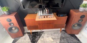
Horrible hum cause found to be a bad driver tube. I thankfully had one spare. The amp is near silent now. Hooked up to my Yamaha garage speakers and my Eversolo DMP A6 it is sounding extremely good right now! Can’t wait to finish the chassis and get it hooked to the big JBLs.
Haha. Maybe if I ever find the elusive 400W Plitrons for sale.So we should be able to hear it from space soon?
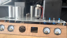
Counter productive, but I couldn’t help myself to take it to my basement and try it out. Absolutely in love with it, although there’s still much work to be done:
-NFB isn’t hooked up yet - that’s getting a pot and a disable switch
-Master volume isn’t wired in yet
-Chassis sides and back need to be finished
-Magic eye VU meter tubes need to be mounted in front panel
-Chassis plate needs to be anodized
-Transformer covers need tops made and need to be secured properly to the chassis
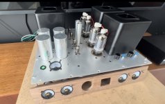
Testing on the big speakers (JBL L100T) went exceptionally well. I did peg the bias meters well past 1V on some heavier bass notes at -16 db input from my music streamer; so I may need 2V meters, or just not worry about it.
Attached are some pictures from the listening session
-NFB isn’t hooked up yet - that’s getting a pot and a disable switch
-Master volume isn’t wired in yet
-Chassis sides and back need to be finished
-Magic eye VU meter tubes need to be mounted in front panel
-Chassis plate needs to be anodized
-Transformer covers need tops made and need to be secured properly to the chassis
Testing on the big speakers (JBL L100T) went exceptionally well. I did peg the bias meters well past 1V on some heavier bass notes at -16 db input from my music streamer; so I may need 2V meters, or just not worry about it.
Attached are some pictures from the listening session
Attachments
Last edited:
XPWR030 - 700V@300mA CT, 130V@100mA, & Dual 6.3V@6A@ChrisM91 I search the threads, what PT and OT did you use to get the 416B+?
CXPP60-6.6K - 60W, 6.6K Ohms push-pull tube output transformer
- Home
- Amplifiers
- Tubes / Valves
- Build Log of 100+ watt Pete Millet “Engineer’s Amplifier”