If you’re not able to go below -30V they are going to be overbiased. I like to start out with enough negative bias to cut them off entirely and bring them up a few mA at a time, monitoring the situation.
Is it possible to run your bias supply separately, bringing up only B+ and Vg2? I like to have a separate transformer for my negative supply, at least while prototyping. Or running a -68V regulated bias rail off -200 or so. Comes up to full voltage by the time you have enough cathode emission to matter.
Is it possible to run your bias supply separately, bringing up only B+ and Vg2? I like to have a separate transformer for my negative supply, at least while prototyping. Or running a -68V regulated bias rail off -200 or so. Comes up to full voltage by the time you have enough cathode emission to matter.
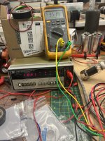
I will try to bring it up separately. I just brought it up to full power somewhat quickly, got only -50V bias (it was 59V when tested without the tubes), current climbed quickly towards 100mA, so I shut it off. I would think this would be enough for 6HJ5s at 630V on the plates, but maybe not.
They are tough tubes, but 50 watts plus at idle is kinda pushing it a bit. 😉
jeff
jeff

So after trying to brute force the problem away with another transformer for C- giving -80V, and having the same result, I had to admit to myself the possibility of a mistake! Turns out my bias pots that are spec’d in the BOM to 10k were only 100 ohms. Thankfully I had a couple spare 10k pots, so I wired them in. Idle current still a bit too high, so I put the second bias transformer back in. That was the ticket and equaled -45V measured at the grid.
Tried for a nice glow picture, but I can’t dim the lights in my garage.
Now to clean it up a bit and test some sine waves.
Tried for a nice glow picture, but I can’t dim the lights in my garage.
Now to clean it up a bit and test some sine waves.
Attachments

Last edited:
There’s a couple 10k resistors and half the balance pot to go through first, so only a few volts on the pot when 100 ohms. Thankfully nothing smoked, yet…
No, they’re 230V. Part number AS-2T230. One of them powers the board, the other is in series powering the plates. Both full bridges. Similar to this picture I found, with the only difference being different diodes, capacitors and a thermistor.

I can’t recall who posted this to give credit, but I think George of tube lab came up with the idea.
This is what it added up to for plate voltage.

I can’t recall who posted this to give credit, but I think George of tube lab came up with the idea.
This is what it added up to for plate voltage.
Last edited:
Two in series, so you don’t drop as much on the g2 regulator. Bought the T-shirt there too. With that option, they don’t even need to be the same voltage.
The 2T230 and 2T300 are very nice to have lying around on the bench, as is the 1T175. With those on hand you can prototype almost anything. George has that good 600V 1+ amp bench supply at his disposal. The only problem with that is good luck finding a transformer that stiff for a real world build. I prefer real iron for that reason - it gives a more realistic look at power supply sag.
The 2T230 and 2T300 are very nice to have lying around on the bench, as is the 1T175. With those on hand you can prototype almost anything. George has that good 600V 1+ amp bench supply at his disposal. The only problem with that is good luck finding a transformer that stiff for a real world build. I prefer real iron for that reason - it gives a more realistic look at power supply sag.
Did some testing this afternoon. Bias current settled in nicely.
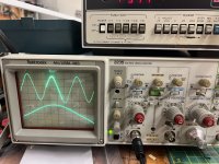
Seems to be a major issue though. Clipping (maybe noise) starting at anything above 1v p-p sine wave input. Tested 1 kHz and 6 kHz with similar results. 0.9 v p-p input gives about 20v p-p output across the 8 ohm dummy load. Square waves look atrocious. Only tested the right channel for now. Any thoughts on next steps?
I didn’t get a picture of the sine wave output at 1v p-p in, as I didn’t want to damage anything, but it looked like noise on the top and bottom peaks, not flat spots.
Edit: sine wave picture at 0.8 vp-p in, square wave at 0.4v p-p in. Scope 1x leads on 5 v/division
Attachments

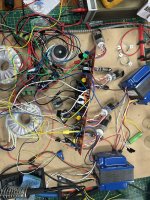
Small update. I figure the majority of the issue is noise due to the spaghetti of wires I have right now, so I decided to press on. Hooked up some input jacks as close to the board as possible, and some cheap Yamaha bookshelf speakers I have in my garage.
The only source I have right now is an old blackberry. Hooked the blackberry up to the inputs and let it rip. -quite disappointing sound, but it worked. Very low volume and flat sounding, lots of hum.
Then this morning I pulled out my HK preamp and hooked the blackberry to it, and used some shielded cables to the amp. Wow! This thing rocks now. Played around with it for half an hour or so with everything from Miles Davis to Rob Zombie. Fantastic sound. Gain is a little low, but I could easily push it to the limits of my little Yamahas.
Next step is to play around with the plate load and schade resistor values to bring the gain up some. Wish I had access to distortion measuring equipment, but alas I’ll have to rely on my ears if these changes hurt the sound. My 6LW6 tubes should arrive this week; I’ll get those wired up and start on the chassis.
I did check that initially, but I sure should check it after running. Thanks for the reminder. It’s a bit torn down right now to tidy up the wiring.
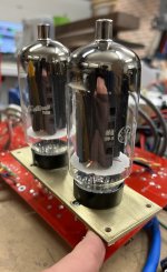
The new tubes arrived today. Here’s a comparison to the 6HJ5s. Still waiting on the sockets to arrive.

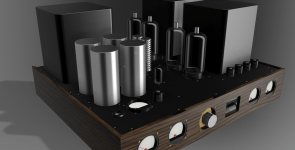
Made a quick rendering of the layout. I’m looking for people’s opinions on whether or not this is a bad idea to place the power supply like this, and also if the heat sinks for the mosfets (the two aluminum rods in the middle) will get too much heat from the power tubes.

Thanks
Made a quick rendering of the layout. I’m looking for people’s opinions on whether or not this is a bad idea to place the power supply like this, and also if the heat sinks for the mosfets (the two aluminum rods in the middle) will get too much heat from the power tubes.
Thanks
I have built 2 "standard" Pete's amps and they heat a lot. Tubes, power tranny, top plate with heatsink, everything gets very hot after a few hours. I would suggest not to cramp things too much if you wanna be able to run it without a fan. In summer the problem is worse (no air conditioning) and the power tranny starts to buzz.
Speaking of this, maybe a fan inside the case, running at half speed, flowing air through holes of the top plate would be the best way to keep the amp a decent size and at the same time be able to have the components so close of each others without having it too hot.
Speaking of this, maybe a fan inside the case, running at half speed, flowing air through holes of the top plate would be the best way to keep the amp a decent size and at the same time be able to have the components so close of each others without having it too hot.
There's a very good argument to make G2 stopper resistors as fragile as possible, with the intent that they fail open (fuse) in case of some catastrophic failure somewhere around the valve. I've seen the well-intentioned use of 5W Dale wirewounds in a Dyna Mk6 pair melt a whole lot of output valves that could have otherwise possibly survived. If these resistors open there's a performance issue, but no other drama.How close should these grid stoppers match? Had to parallel four 1/2W resistors to get 2W. Resistance ranges from 520 to 570 ohms.
View attachment 1250006
All good fortune,
Chris
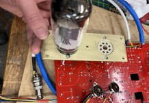
My octal sockets finally came in the mail, so I was able to measure them up and cut some output tube mounting plates. These plates will be mounted to the bottom of the top plate. I’ll cut the holes a little larger in the top plate to expose some of the brass.
I’ll have to paint or anodize the top plate to avoid galvanic corrosion with the aluminum, but I think it will look good.
The screws are just temporary, I’ll get nicer ones; I only stock metric hardware, and the sockets require imperial.
I’ll have to paint or anodize the top plate to avoid galvanic corrosion with the aluminum, but I think it will look good.
The screws are just temporary, I’ll get nicer ones; I only stock metric hardware, and the sockets require imperial.
Attachments

You could put some .030" thick nylon washers in between the plates if that's a concern. Still paint the top plate thou. 🙂I’ll have to paint or anodize the top plate to avoid galvanic corrosion with the aluminum, but I think it will look good.
jeff
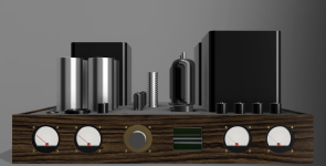
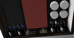
Progress has slowed somewhat, but still working away at it. The next step I think is to cut the chassis plate, as I realized after redoing my tube socket wiring, I made the wires too short. Need to get it all mounted so I can make it right. I took some time to make a proper render of the design (proper for me anyway, I'm no expert in modeling) so I can check fitment, interferences, and overall look. I'll use this design to cut the parts from in the coming days. As you can see, it's a tight fit underneath, but should be just enough room to actually assemble it. I've left just enough room for a small fan in front of the heat sinks if that proves necessary.
Attachments
Last edited:
Interesting approach to turn the board 90° from its "original" orientation. Looking forward for the finished look.
A standard engineer amp is heavy, this one wiĺl be more heavy if you scaled the iron for 100W... you need to think about lifting it, moving it, turning it upside down for servicing, etc. I have one leftover big red board, who knows what you will initiate here... 🙂
A standard engineer amp is heavy, this one wiĺl be more heavy if you scaled the iron for 100W... you need to think about lifting it, moving it, turning it upside down for servicing, etc. I have one leftover big red board, who knows what you will initiate here... 🙂
- Home
- Amplifiers
- Tubes / Valves
- Build Log of 100+ watt Pete Millet “Engineer’s Amplifier”