Markaudio advertizes it's drivers as fullrange... Off-axis shows how that is done, by a wobbling shallow cone. Nice distortion still.

Offsetting mid and tweeter from midline would be wise... 6dB sharp dip would be avoided and mild offset wouldn't spoil offaxis responses

Offsetting mid and tweeter from midline would be wise... 6dB sharp dip would be avoided and mild offset wouldn't spoil offaxis responses
Last edited:
Anyhow, looking at the whole package - 15W looks the best to me out of the three.
Most sensitive, pretty flat frequency response, relatively benign breakup. It does have rising HD3, but if we take into account that crossover will be around 2kHz (usually -6dB point) HD3 might not be a problem after all. Also, going from 86dB to 96dB, the HD3 peak rose about 3dB. Ideally it wouldn't budge at all but this is also quite good in my opinion.
For tweeters, XT25 is worst of the bunch regarding frequency response. It drops like a stone off axis. Distortion is great in all three. Either 26ADC or 26STAC - both look great considering measurement conditions.
The crossover may not be too different for finished loudspeaker and that could be optional - alu or silk dome, per one's taste.
Last edited:
Mid centered / offset 8cm (blue), 20cm from top / Baffle 40x65cm

MTW configuration, centered / offset 8cm (blue), 10cm from top / Baffle 40x65cm

Tweeter SB26ADC 7cm from top, centered / offset 8cm (blue), 7cm from top / Baffle 40x65cm

Tweeter SB26ADC 7cm from top, MTW configuration, centered / offset 8cm (blue), 20cm from top / Baffle 40x65cm

MTW configuration, centered / offset 8cm (blue), 10cm from top / Baffle 40x65cm
Tweeter SB26ADC 7cm from top, centered / offset 8cm (blue), 7cm from top / Baffle 40x65cm
Tweeter SB26ADC 7cm from top, MTW configuration, centered / offset 8cm (blue), 20cm from top / Baffle 40x65cm
Offsetting mid and tweeter from midline would be wise... 6dB sharp dip would be avoided and mild offset wouldn't spoil offaxis responses
In that sense, I have made some averaging of the on-axis and off-axis responses from Response Modeler.
Each averaged graph represents 41 curves, 1 on-axis and 40 off-axis, set apart 5 deg. Offset to one side,
there is a slight improvement over the centrally positioned driver. Baffle edges were sharp.
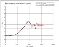
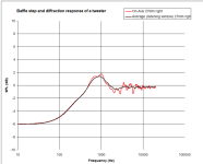
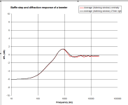
Yeah vituixcad diffraction tool can export the data, full spin so one can watch polar maps and power / DI. One can there see how much response changes per observation angle, or EQ some axis flat to see what response is then on the others.
This size baffle is the worst scenario for the midrange. Only same diameter round would be worse, with central driver. As we see in measurements, all off-axis responses have the same dip, it is so dominant.
And this is why most vintage large speakers had offset mids and tweeters. Stereo pairs are/were mirror images and the end user has the chance to try which is better in her room - MT in/outside. And there is slight possibilty that one might even hear the difference!
And this is why most vintage large speakers had offset mids and tweeters. Stereo pairs are/were mirror images and the end user has the chance to try which is better in her room - MT in/outside. And there is slight possibilty that one might even hear the difference!
Same distance to three edges is worst case scenario. I would not chose 20 cm from top for any of the drivers with a 40 cm wide baffle.20cm from top / Baffle 40
But I guess you wanted to show exactly this!
Once we have drivers selected we'll finalize the dimensions. There are several things that will restrict our choices, so I don't anticipate a lot of flexibility.
@A4eaudio
I wanted to say something polite and nice about all the drivers, because they all perform reasonably well.
But frankly, they also perform reasonably unwell. So whilst all driver were measured properly by yourself under the same fair conditions, ie. same voltage drive level, on same cabinet, and thus can be compared to each other, it's clear that baffle size and midrange driver placement is creating on and off axis havoc with the frequency response. As you know, this affects apparent harmonics measured too.
If we want to select drivers BEFORE choosing cabinet dimensions, or BEFORE deciding on placement, please consider bringing the mic to the middle of each driver cone, within a distance of radius / 2, and take a nearfield measurement?
I'm reminded of something the loudspeaker designer Jack Hidley once said:
“The first step in looking at any speaker system, is to take nearfield measurements of the individual driver outputs. This tells you what the driver is doing and removes almost all of the room acoustics effects and some of the cabinet affects. Doing anything else first is a waste of time”
Last edited:
Your measurements are great and quite revealing. I do think you should have done diffraction simulation before mockup cabinet and then position transducers accordingly...
I had done the diffraction simulation before hand as had somebody else. I think we all have a pretty good idea of what the diffraction of the centered driver vs offset looks like. I deliberately measured with the centered driver to see how BAD it is with actual measurements because we know we can move to offset if needed.
Here are the midranges, with psychoacoustic smoothing and 50dB/decade. The 15W/4434 has a narrow 2dB dip that covers about 1/4 of an octave. If we wanted to use centered driver, we could live with this. I'm not sure I can say the same about the other two.
Last edited:
By the way, I am not deliberately leaving out the FaitalPRO and Peerless 5-inch drivers that we had listed, I just don't happen to have them.
Also, with regards to sensitivity...The CHP-90 only comes in 8-ohm. I bought the SS 15W last week so deliberately bought the 4-ohm. The SB15MFC-08 I already had, but if we selected that driver we could choose to go with the 4-ohm version.
Also, with regards to sensitivity...The CHP-90 only comes in 8-ohm. I bought the SS 15W last week so deliberately bought the 4-ohm. The SB15MFC-08 I already had, but if we selected that driver we could choose to go with the 4-ohm version.
You are way ahead of me, @A4eaudio, I just yesterday bought some foam board to start a baffle for the SB12MNRX2 driver. So it will be at least a week before I have data to post.
Based on what you posted, I can say that I wish the ScanSpeak 15W had lower HD3, because the choice would be easy.
Based on what you posted, I can say that I wish the ScanSpeak 15W had lower HD3, because the choice would be easy.
...If we want to select drivers BEFORE choosing cabinet dimensions, or BEFORE deciding on placement, please consider bringing the mic to the middle of each driver cone, within a distance of radius / 2, and take a nearfield measurement?...
Just to make sure I am reading this correctly...take one on-axis measurement about 1-1/4 inch from the driver?
50 pages and nothing really decided on, now this is the kind of signal to noise ratio I live for on here lol.
What is the limit of pages? Did we miss a deadline that I'm not aware of?
We decided on the woofer, it will be in stock at PE in May so I have that as an informal deadline to have the midrange and tweeter selected. I'm pretty sure we'll meet that deadline. 😁
We decided on the woofer, it will be in stock at PE in May so I have that as an informal deadline to have the midrange and tweeter selected. I'm pretty sure we'll meet that deadline. 😁
There is none!What is the limit of pages?
That's the great thing about a forum.
I mean, what's next, a Dynaco A25 reboot (10" + 1.3" 2-way) ?
B&W Nautilus ! 😀
Just to make sure I am reading this correctly...take one on-axis measurement about 1-1/4 inch from the driver?
The convention to measure the cone diameter from one side to the other. Many ?most manufacturers also cover part of the surround, from one side to the other.
So something marketed as a 6" midwoofer will typically have a cone diameter of 5", if we look at apex to apex: eg. SB17NAC as below.
Depending on whether they take 1/3 to 1/2 of the surround depends on manufacturer, but this is how they come up with the "Effective Piston Area"
(Sd)
Now as an aside, it's only recently that Carsten and Lars from Purifi discovered/documented that the surround contributes a significant proportion of distortion, because a) it's very non-linear, and flaps/farts in the wind (literally). All this time manufacturers have been flip/flopping and changing cones to optimize for stiffness vs damping, yet seemingly forgotten that the surround contributes too, as a sound emitter.
It does this by causing changes in the surface area of the emitter, depending on excursion.
Purifi call this Surround Radiation Distortion- as the cone goes inwards the Sd is at it's maximum, as the cones moves outwards, Sd is at it's maximum.
Try and see this for yourself:
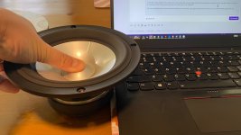
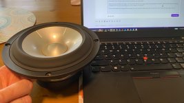
At some point Klippel and company will/have acknowledged this and probably call it Sd(x), along with their big three causes of distortion Bl(x), Cms(x) and Le(x).
Anyway, I digressed.
You can put your microphone as close as you want, but please don't put it so close that you can accidentally damage your cone or microphone
(ask me how I know). So for a tweeter it could be a few millimeters, for a midrange a few centimeters, for the big subwoofer with long excursion, a couple of inches. You just don't need to be right up against it, to be in the nearfield (Fresnel zone)
Last edited:
I generally take near field measurements of cones at a distance of 1/4 inch or 6 mm. I use a very reduced drive level because even with 0.1 V, the SPL at the microphone is usually close to 100 dB SPL. The information I want from a NF scan can be revealed with a low signal.
For tweeters, I get as close as I can get, 2 mm or less. But I am careful, both tweeters and measurement microphones are delicate... ask me how I know 🙄
For tweeters, I get as close as I can get, 2 mm or less. But I am careful, both tweeters and measurement microphones are delicate... ask me how I know 🙄
- Home
- Loudspeakers
- Multi-Way
- Budget Classic 3-way Discussion Thread