Fetamps measurements also suggest that the driver Q17 mje15030(npn) has a lower hfe than its counterpart Q18 mje15031(pnp). This is indeed the case; all of the npn transistors in the mje1503x series that I have measured have a much lower hfe than their pnp complements. I can't find any currently available devices which go any way to solving these problems. However it may prove possible to use TIP35C and TIP36C for the output devices as they have a sufficiently low ft (3mHz) and I have a few matched npn/pnp pairs with an hfe of about 100. Vceo(min) is only 100V but my measurements give about 130V for th TIP35C and 200V for the TIP36C, so good for up to +/-60V power supply. The devices I have are pretty old so I'll but some modern ones and check them out.
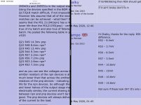
Congratulations chalky.....please post some clicks.......I will post my values vs Trampo’s please comment it...why similarities?
Attachments
Last edited:
Similarities are because modern semiconductor production methods are remarkably consistent - all the npns tend to be very similar as do the pnps. It was really only the Japanese that selected for hfe(transistors) or Idss(jfets) and they've largely stopped manufacturing now. So getting any kind of npn to pnp match is that much harder. Maybe even harder if Bryston is skimming the best matches off the top of the devices used in their power amps. Matching of npn to pnp devices doesn't make a lot of difference in the case of most output stage topologies but it does with the Bryston and results in lower distortion and better current sharing amongst the output devices.
Congratulations chalky.....please post some clicks.......I will post my values vs Trampo’s please comment it...why similarities?
Both of us highest in R49 and lowest in R57.....?
Hi all....please let me know can I use B1565/d2394 or mje340 /350 instead of mje182/172 in input module output stage?. Please don’t worry about pin configuration.
The mje340/350 would be ok but not as good as the mje172/182. The B1565/D2394 pair are TO220 and have a different pinout to the TO126 devices - the Vceo of 60V is a bit iffy with +/-33V supplies too. If you remember I used the KSA1220A/KSC2690A pair ( mainly because I could get a good npn/pnp match ) and these perform very well.
Thanks a lot chalky....because of lockdown I can’t find mje or good BD140, how would be the performance of B1565/D2394 pair as I have nearly matched pairs?.
Those are for new version of large input module,I’m mainly worrying about gain of input module. I need to have enough gain to obtain maximum output from power amp.
Those are for new version of large input module,I’m mainly worrying about gain of input module. I need to have enough gain to obtain maximum output from power amp.
The B1565/D2394 pair will probably work fine - but remember the reversed pinout compared to TO126 transistors. As regards the 60V Vceo with a 66V power supply; you'll almost certainly get away with it. The Vceo specified on datasheets is the minimum, and in my experience this is almost always comfortably exceeded with real devices. In fact I, personally, have never come across a transistor that doesn't exceed the minimum by at least 5%. Bear in mind too that you're never going to drive the input amp to full output in this application. However, having said all of that I tend to be (over)cautious and wouldn't use devices with a Vceo of less than 80V in this case.
Thanks Chalky ....planed to use it in output stage only ,for the regulator ,will try another option.
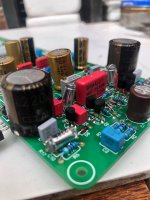
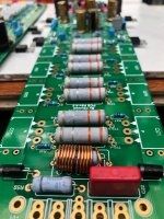
My bryston 4b sst clone!!
Y have to finish matching transistor y debugging process.
And a chassis to house everything.
Y have to finish matching transistor y debugging process.
And a chassis to house everything.
Attachments
-
 amp4 pcb.jpg191.2 KB · Views: 340
 -
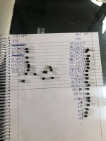 matching transistor.jpg195.9 KB · Views: 339
 -
 psu2 pcb.jpg221.9 KB · Views: 308
 -
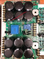 psu pcb.jpg416.9 KB · Views: 317
 -
 input2 pcb.jpg223.4 KB · Views: 306
 -
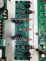 input pcb.jpg378.9 KB · Views: 499
 -
 amp1 pcb.jpg261.7 KB · Views: 539
 -
 amp3 pcb.jpg268.2 KB · Views: 557
 -
 amp2 pcb.jpg244.6 KB · Views: 576
 -
 amp pcb.jpg454.8 KB · Views: 588
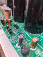
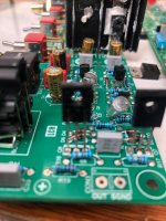
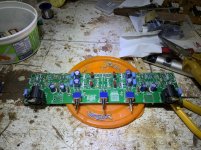
Congratulations hschier ,nice job...please share your experience with us ,please let me know about Q5,6 in input module are they hot to Tuch? Please post some pictures of AMP cabinet,
Last edited:
i replaced pn100/pn200 for bc550/bc560, that's why they are installed backwards.
i will share my progress. thanks!!
i will share my progress. thanks!!
Congratulations on your build, but from the photos it looks like your soldering could use a little more heat,
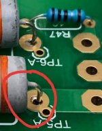
thanks Thomas!!! only expert ayes. Thanks
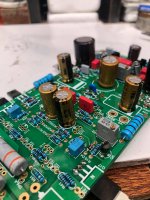
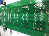
I reflowed all of them. here is the pic from back.
I reflowed all of them. here is the pic from back.
Attachments
Last edited:
- Home
- Amplifiers
- Solid State
- Bryston 4B SST clone