Thanks Chalky....what is your opinion,can I drive my AMP safely in high output level with above values? And please explain whether this AMP design is to Switch on Q19,20,21,22 at first and other 4 later ?
Thanks
Thanks
No the outputs all switch on together. One set are driven from the emitters of Q17/18 and the other set from the collectors of Q17/18. The idea is that you have both npn and pnp output devices switched on at both the upper and lower half of the output cycle. I suspect your amp will be ok but you'll just have to try it I'm afraid.
Сhalky , I want to ask, does the VAS current greatly affect the quality? There is no way to measure it, the card is bad. I want to reduce it to 3mA by replacing 150 ohms with 220 ohms.
This applies to the input board
This applies to the input board
Last edited:
If you replace the 150R vas emitter resistors with 220R you will reduce the vas current from 12mA to 8mA and also reduce the standing current in the output transistors. If you look back through this thread you'll see that I presented a modified input stage with reduced dissipation in Q5/6.
Thanks Chalky......i will try to match much as possible...I put heat sinks to Q5/6 and started to run the AMP ,don’t know will burn the input module 😀
Here is Bryston's explanation of how their output stage works. As you can see we don't get optimum performance from our clones because its next to impossible get a MJL21193 and MJL21194 pair with matching hfe.
How can bryston get perfect hfe matched power transistors ?
Generally it is impossible to have N P MATCHED powered devices·
Bryston don't use off the shelf transistors, they have their transistors custom hfe matched by the manufacturer. One of the reason why Brystons are so expensive. I haven't looked around but it may be possible to get low ft power devices where a reasonable hfe match is possible for the npn and pnp devices. Fetamp I think your input boards will be ok, particularly with Q5/6 heatsinked. I soak tested my input board with no heatsinks and a sinewave input for a few hours and they were fine. But if you're worried then go with the mods I suggested.
If a semi firm can produce matched n p pairs of power trs to Bryston,
How come they don't sell matched pairs to other electronics businesses?
How come they don't sell matched pairs to other electronics businesses?
They won't do this because it's Bryston. Bryston will get "prefiltered" batches of matching pairs. That's what pushes the costs.
Are there any proof Onsemi will do such an advantage to the so called audio amplifier company ? I mean the comsumption amount is very little to affect Onsemi to do so
Few clicks at the end ....thanks for all specially Chalky and Amplidude
Attachments
-
 A64AFE7A-40B2-48EC-BCB8-1A47AB22E00E.jpeg403.6 KB · Views: 490
 -
 ACA3A80E-0FC3-40B6-8F80-361A5D0E5CD9.jpeg343.7 KB · Views: 494
 -
 B972917A-6A03-45EA-95A4-6853A33CE9FB.jpeg395.4 KB · Views: 485
 -
 F67FBAA8-993C-4E59-8941-A673070EDA1A.jpeg421.7 KB · Views: 469
 -
 1B5BF51D-DFA5-4BA7-89BC-ADA3A7612CB7.jpeg246.2 KB · Views: 457
 -
 1CE4F210-E581-4BA9-A4BD-C7741F000ED6.jpeg317.1 KB · Views: 234
Last edited:
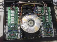
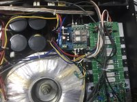
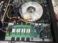
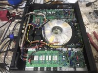
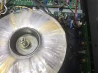
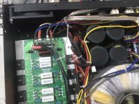
Nicely done fetamp. Did you reuse an old case? Kudos for using the Speakons. Are they fans at the back of the case - do you use them?
Thanks Chalky....yah...old case,old psu from Two different power amp...output through speakons,installed two fans as poor matching of OP transistors will produce extra heat...for little safe side?
More progress. I've attached a photo of my nearly completed power supply and protection board. I'm going to fix heatsinks to the bridge rectifiers, and make up a couple of solid state relay pcbs to replace the loudspeaker protection relays. I'll make them with the same footprint and connections as the mechanical relays so that they are a drop in replacement on the main pcb. Initially I'll make them up on small pieces of perfboard and then later on I'll do proper pcbs.
Hi Chalky,
Did you install C11 C12 C23 y C24 104 1000V? In Pcb are drawn below.
thanks
No I didn't. Ideally there should be a damping resistor in series with each capacitor. In retrospect I'd also have installed individual soft recovery diodes instead of the bridge rectifiers.
Last edited:
No, the purpose is for interference suppression - the rectifier diodes produce rfi when they switch. See the "Rectifier Diode Snubber" thread on this forum.
I use a panasonic or nichicon bipolar capacitor. These are very low distortion and I doubt I could tell the difference with or without; although I haven't tried it. I prefer a capacitor in this position as a preamp with a dc coupled output ( like the Bryston clone input boards ) could turn your expensive power amp into a smoking ruin if it developed a dc fault. Omit the capacitor and trim the power amp dc offset to compensate for any dc on the preamp output - but on your own head be it - I wouldn't do this.
- Home
- Amplifiers
- Solid State
- Bryston 4B SST clone