Not sure we're talking about the same thing here. The 4B SST power amplifier has a gain of about 14 and the separate input module has a gain of 2, single ended. The gain of the power amp by itself is a bit low without an input module. If you want to dispense with the input module you can increase the power amp gain to 20-30 by altering the feedback resistors. I'm not sure which schematic you're referring to.
Hi.chalky ...please let me know how to change feedback resistors in order to increase gain...
As regards Q5/Q6 of the input module they are dissipating a bit less than 400mW and the devices are rated at 625mW; so within spec but still a bit too hot for comfort. Possible solutions are heatsinks, use to126 devices and juggle with the pinout, or rejig the circuit as I detailed in an earlier post. As for changing the gain you can try increasing R14 to 10k or 12k, but I haven't tried this myself.
I tried it with TO-126 at a current of 10mA, the norm. But the problem with pinout, connected with conductors.
Perhaps I will make a new wiring for the PP.
Experienced other input schemes, which are better metrologically. The clone of the input sounds better.
Perhaps I will make a new wiring for the PP.
Experienced other input schemes, which are better metrologically. The clone of the input sounds better.
Last edited:
May I ask a questions why you want to replace the pn100/200 transistor? I was asked the PCB Designer once , and he said that this transistor is easy to buy in China, so it has not been replaced.
The 2n are much cheaper, and available everywhere, buy hundreds and you can find good pairs, I believe that's the reason.
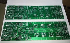
Any of you guys seen/tried these amplifiers? Designed by the same guy who did the Bryston 4B SST boards. They seem to be a more conventional design so I've bought a couple to see what they're like.
Pair of 400W+400W Stereo Power Amplifier PCB Board based on YBA P100 Amp C 2.0 | eBay
Pair of 400W+400W Stereo Power Amplifier PCB Board based on YBA P100 Amp C 2.0 | eBay
Attachments
Hi.
Yes I have also had my eye on those French clones, that guy chywen makes some pretty decent boards, the rewiev in stereophile was very promising as I remember.
Have you got a new tickle chalky? 🙂
Yes I have also had my eye on those French clones, that guy chywen makes some pretty decent boards, the rewiev in stereophile was very promising as I remember.
Have you got a new tickle chalky? 🙂
I see that the service manual for the original is available at electrotanya.com, might come in handy,
It's to big file to upload here unfortunately.
It's to big file to upload here unfortunately.
I'm always curious. Had a look at the service manual and can see lots of ways to improve them from an engineering point of view, but what effect this has on the sonics who knows? Given that their distortion spectrum is almost all second harmonic I guess that they sound nice and valve like.
I would consider lowering rail voltages and use lower distortion transistors, and reduce outputs to maybe 4 devices
The clone has a few changes from the original. The input diff pairs are fed from 2T constant current sources rather than a resistor bias chain; the VAS current is upped from 4mA to 12mA; the two 10k resistors hanging off the VAS collectors(!) are (thankfully) gone; the Cdom compensation caps are reduced from 150pF to 30pF; and there are only 4 rather than 8 output pairs. Yes plenty of scope for experimenting with different transistors. Did you ever finish your 28B SST amplitude?
Sounds like chewyn did some nice upgrades already, but aren't crd diodes a bit noisy, could be a future project.
No I dropped the big bryston, the parts price was to much, chassis heatsink etc, I've been fiddling with jlh and hiraga amps lately, this class a stuff is quite addictive, and not so complex.
How about your 4bsst? Is it singing?
No I dropped the big bryston, the parts price was to much, chassis heatsink etc, I've been fiddling with jlh and hiraga amps lately, this class a stuff is quite addictive, and not so complex.
How about your 4bsst? Is it singing?
Sorry should have been less cryptic - I meant 2 Transistor rather than 2 Terminal. Getting there with the 4bsst; just finalised the case details. I'm going to mount the amp modules on thick Al plates which ( removeably ) screw to the heatsinks. That way I can try out different amp modules whilst retaining the same psu, protection, etc
Hi...please explain why voltage differences across
R49 -14.3mv
R48-8.6mv
R45-13.4mv
R44-9.3mv
R57-2.2mv
R56-7.2mv
R53-2.8mv
R52-7.3
Is it normal or any faults?
Thanks
R49 -14.3mv
R48-8.6mv
R45-13.4mv
R44-9.3mv
R57-2.2mv
R56-7.2mv
R53-2.8mv
R52-7.3
Is it normal or any faults?
Thanks
It tells you that the output devices aren't matched. Probably nothing wrong. If you have an ac millivoltmeter ( good for 1kHz ) you could try measuring the ac voltages across these resistors when the amplifier is delivering some power ( say 10-20W at 1kHz ). This will show you how well the current sharing is working. Ideally you should match all of the npn output transistors as well as possible and then do the same, separately, for the pnp devices. You would be extremely lucky to get the npn devices to match the pnp devices so don't worry about it.
Thanks chalky I was waiting for you...as you said i matched the transistors as much as possible.please note hfe/vbe
117/.524mv
111/.535mv
108/.515mv
111/.525mv
NPN
45/.537
43/.535
39/541
41/..535mv
Please give your valuable input Chalky.this done by Chinese transistor tester
117/.524mv
111/.535mv
108/.515mv
111/.525mv
NPN
45/.537
43/.535
39/541
41/..535mv
Please give your valuable input Chalky.this done by Chinese transistor tester
On the surface that doesn't appear to be too bad, but, you really need to match the transistors at a more realistic current, say 1A. The various Chinese transistor testers measure the hfe and Vbe at very low currents, usually of the order of a few hundred uA to one or two mA. There a few threads here which tell you how to match power bjts and mosfets at realistic currents. Maybe amplitude will let you know what his corresponding measurements are. When I get my power amps fully set up I'll publish a schematic with as many key voltages and currents as I can fit on the diagram.
Hi again, I can't find the notes from build, but found this test jig at leach site, it measures Hfe at higher currents, I used mjl21193/94, from a used high quality amp, so they are same batch, they were pretty close.
Could you not change base resistors, if one output is pulling more current, notch up the base resistor a bit, quite a puzzle it is.
The Leach Amp - Part 2
Could you not change base resistors, if one output is pulling more current, notch up the base resistor a bit, quite a puzzle it is.
The Leach Amp - Part 2
fetamp, I measured a few of my MJL21193/4 with a transistor tester and got similar hfe Vbe to you. The npn hfe was a bit higher and centered around 50 whilst all of my Vbe values were a bit higher than yours at around 600mV. Don't read too much into the differences as these Chinese testers aren't exactly the last word in accuracy. They seem to give best results when fully charged.
- Home
- Amplifiers
- Solid State
- Bryston 4B SST clone