Enrico,
I mentioned that the red wire in the flat cable should be the 5Volt.
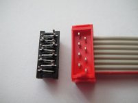
However, I'm not so sure if this is correct, since the plug is keyed and can only be plugged in the female connector in one way and the documentation from TE is very minimal.
I'm afraid you will have to buy this female plug to be 100% sure.
Since I'm on holiday at the moment, I cannot be of much help at the moment.
On the other hand, when your PCB layout is exactly the same as on the VolCB, it cant,t go wrong.
Hans
I mentioned that the red wire in the flat cable should be the 5Volt.
However, I'm not so sure if this is correct, since the plug is keyed and can only be plugged in the female connector in one way and the documentation from TE is very minimal.
I'm afraid you will have to buy this female plug to be 100% sure.
Since I'm on holiday at the moment, I cannot be of much help at the moment.
On the other hand, when your PCB layout is exactly the same as on the VolCB, it cant,t go wrong.
Hans
Last edited:
Enrico,
I mentioned that the red wire in the flat cable should be the 5Volt.
However, I'm not so sure if this is correct, since the plug is keyed and can only be plugged in the female connector in one way and the documentation from TE is very minimal.
Hans,
I see your note but, as you said, who drive is the reference point and the red wire is on the same side.
I'm afraid you will have to buy this female plug to be 100% sure.
Since I'm on holiday at the moment, I cannot be of much help at the moment.
I had the same though and I ordered few of them last week.
Those connectors are really tricky and the datasheets doesn't help at all!!!
I just get the female and just finish to test point to point the cable with the connector. Result: I need to revise the PCB again and back at the first design.
In the picture attached you can see that the point that in the cable is in the left side is moved by the female connector to the right side (and vice versa).
On the other hand, when your PCB layout is exactly the same as on the VolCB, it cant,t go wrong.
Actually is not... attached is a sketch where you can see the real tested connections between the 2 PCBs.
I hope that this is the latest final revision of the PCB.
Enjoy your vacation and Best Regards,
Enrico
Attachments
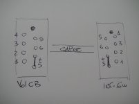
What a mess.Hans,
I see your note but, as you said, who drive is the reference point and the red wire is on the same side.
I had the same though and I ordered few of them last week.
Those connectors are really tricky and the datasheets doesn't help at all!!!
I just get the female and just finish to test point to point the cable with the connector. Result: I need to revise the PCB again and back at the first design.
In the picture attached you can see that the point that in the cable is in the left side is moved by the female connector to the right side (and vice versa).
Actually is not... attached is a sketch where you can see the real tested connections between the 2 PCBs.
I hope that this is the latest final revision of the PCB.
Enjoy your vacation and Best Regards,
Enrico
Glad you had the cables in your hands.
Kind regards
Hans
Dear All,
I have some good news but one bad news...
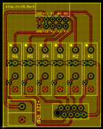
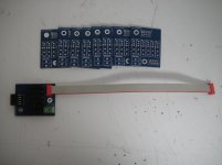
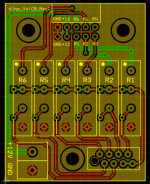
The boards have been received yesterday. I built one quickly to test the connection with the Maya and everything is fine but I was so concentrated in the input connector that I forgot to recheck the output for the 6 input board. Unfortunately the output are reversed.
I already redesigned the board and I will send the new order today.
Attached are a picture of the boards with the one I tested and the revised pcb.
I am sorry about that but I am sure that I can get the new pcbs quickly and be able to send out the boards before I leave.
Best Regards,
Enrico
PS: The boars with relays is quite heavy, so I added few holes that can be useful to install a standoff and release the load from the connector in the 6 input board.
I have some good news but one bad news...
The boards have been received yesterday. I built one quickly to test the connection with the Maya and everything is fine but I was so concentrated in the input connector that I forgot to recheck the output for the 6 input board. Unfortunately the output are reversed.
I already redesigned the board and I will send the new order today.
Attached are a picture of the boards with the one I tested and the revised pcb.
I am sorry about that but I am sure that I can get the new pcbs quickly and be able to send out the boards before I leave.
Best Regards,
Enrico
PS: The boars with relays is quite heavy, so I added few holes that can be useful to install a standoff and release the load from the connector in the 6 input board.
Attachments
Thanks for all the effort Enrico. Could we have just soldered the connector on the wrong side or would there not be solder rings?
Hi Nat, unfortunately it's wrong the output connector design.
The board is working but the input 1 activate the out 6, in 2 activate out 5 and so on. No other chance than fix the pcb...
The board is working but the input 1 activate the out 6, in 2 activate out 5 and so on. No other chance than fix the pcb...
Would just renumber the inputs be the same?
Seems a waste to throw away perfectly good boards...
Jan
Seems a waste to throw away perfectly good boards...
Jan
Yeah.. just renumber the inputs on the back panel? It doesn't matter which is which on any board, only matters to the user when they plug things in. There is no reason for the current input 1 to not be input 6 instead, go right to left instead of left to right on the back panel.
Enrico is possibly seeing it from the point of view of someone who has already built his preamp with the 6 input board (because he has) whereas many people will be starting from scratch and so it won't matter.
Enrico is possibly seeing it from the point of view of someone who has already built his preamp with the 6 input board (because he has) whereas many people will be starting from scratch and so it won't matter.
Thanks Jan and Nat... that's true, the problem is only about the numbering of the output in the rear panel and in the 6 input board silkscreen
As Nat pointed out, I don't know how many people in GB have already realized the rear panel and I don't want anyone have any trouble...
Anyway the boards have been reordered so the point is not more under discussion 🙂
Best Regards,
Enrico
As Nat pointed out, I don't know how many people in GB have already realized the rear panel and I don't want anyone have any trouble...
Anyway the boards have been reordered so the point is not more under discussion 🙂
Best Regards,
Enrico
But it does mean there are other boards available at a later date perhaps should anyone want them for a new build...
Today I received the new boards and I will be able to send you the interfaces in few days
Best Regards,
Enrico
Best Regards,
Enrico
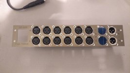
Hey, a long time has passed ... I finally got around to making a back panel for my project in Front Panel Designer using Enrico's 6 input board.
It may be a little premature to upload the file as I have only just placed the order so can't check if it is all ok or not, but hopefully it will be helpful to someone.
My project involves putting everything inside a Quad FM4 case. The back panel of the usual case is too thin and full of other holes to use with 6 inputs (it would become swiss cheese) so I have created another with the idea to cut out the rear steel of the internal chasis and bolt this new back-panel on. For this, there are threaded holes at each end.
I have also added a second set of output socket holes so I can add a tape out at a later date (using a second bpbbp board, internal gain setting).
There are two files attached in a zip (a file format I can attach on DIY Audio), one more basic using the standard XLR template within Front Panel (matches Neutrik A and B chassis shapes) and a second with countersunk M2.5 holes for the XLR mountings (which I need to be flush for the Quad case to slide all the way on).
Anyway, if nothing else, the arrangement of the sockets can be grouped (delete the extra tape output holes first) and re-used for someone else's project! I used Enrico's own .pdf for the spacing measurements.
Attachments
nat, i cured the hum. oddly every eighth step aded more hum. I grounded the chassis of the Khozmo to the xlr input gnd, noise gone. Very happy now.
Warning for my post #174 : There's a mistake in my file..
I managed to miss a 2mm difference in distance between a pair of XLR holes.
Attached is the fixed file (again in a .zip to get around the accepted attachment filters) .. and a photo of what it looks like in the flesh.
I managed to miss a 2mm difference in distance between a pair of XLR holes.
Attached is the fixed file (again in a .zip to get around the accepted attachment filters) .. and a photo of what it looks like in the flesh.
Attachments
nat, i cured the hum. oddly every eighth step aded more hum. I grounded the chassis of the Khozmo to the xlr input gnd, noise gone. Very happy now.
Is the 8th step to do with anything in particular within the design of the Khozmo?
That's great news! A simplified version with knobs only is very welcome, no displays screaming at me.
Are you going to match up case design with your Paradise boxes?
Nat, the issue was a failed relay on one channel, khozmo repaired the attenuator. All sounding sweet now. The case won't be like my paradise boxes, different form factor and metalwork. Should be done in a week, back panel is done.
45156458354_a0bce5869e_o | Schaefner back panel with LEMO OB… | Flickr
45156458354_a0bce5869e_o | Schaefner back panel with LEMO OB… | Flickr
The LEMO connector is for DC in?
- Status
- Not open for further replies.
- Home
- Group Buys
- Bruno Putzeys Preampli - GB for the 6 Input Board