Hi to all,
First module up and running!!!
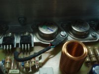
Bias current set to 160mA, offset voltage under 10mV. Main heatsink barely gets worm with no input, predrivers heatsink is at room temperature. For T8 I'm using BD139, mounted on one of the power transistors (close as possible 🙂)...
I already try some music, and very pleased with sound, although with small lab power supply (+-35). Amp is dead quiet with no signal on input (just like his mosfet brother).
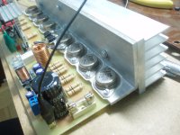
One more module and then mounting all in the case!
THANKS QUASI FOR ANOTHER GREAT DESIGN!!!
Regards,
Miodrag
First module up and running!!!
Bias current set to 160mA, offset voltage under 10mV. Main heatsink barely gets worm with no input, predrivers heatsink is at room temperature. For T8 I'm using BD139, mounted on one of the power transistors (close as possible 🙂)...
I already try some music, and very pleased with sound, although with small lab power supply (+-35). Amp is dead quiet with no signal on input (just like his mosfet brother).
One more module and then mounting all in the case!
THANKS QUASI FOR ANOTHER GREAT DESIGN!!!
Regards,
Miodrag
Attachments
Congratulations Miodrag,
You have done a great job. Soon you will be able to tell us how the bi-polar amp compares to the MOS amp.
Good luck with the rest of the build.
Cheers
Quasi
You have done a great job. Soon you will be able to tell us how the bi-polar amp compares to the MOS amp.
Good luck with the rest of the build.
Cheers
Quasi
Nice!
Miodrag, how did you wind (and keep) that coil so perfect.
I have got to get back to building my NBIP. Not enough resistors yet. Sometimes I feel like I collect resistors, and just build amps for some place to store and organize all the resistors.
..Todd
Miodrag, how did you wind (and keep) that coil so perfect.
I have got to get back to building my NBIP. Not enough resistors yet. Sometimes I feel like I collect resistors, and just build amps for some place to store and organize all the resistors.
..Todd
taj said:Nice!
Miodrag, how did you wind (and keep) that coil so perfect.
I have got to get back to building my NBIP. Not enough resistors yet. Sometimes I feel like I collect resistors, and just build amps for some place to store and organize all the resistors.
..Todd
I know what you mean Todd. I have a few finished and unfinished PCB's myself. Some are in perfect working order without their stereo partner. Others work but just aren't up to scratch. The rest range from half built to some that turned black on switch-on. Oh well ..... 🙄
Cheers
Q
It's like collecting sports cards. You're always missing that one hard-to-find player so your team remains incomplete, and your collection is worthless without it.
Enough analogies. Back to eBay to look for the missing 1957 Topps Bobby Hull rookie card, I mean 47 ohm resistors.
..Todd 😎
Enough analogies. Back to eBay to look for the missing 1957 Topps Bobby Hull rookie card, I mean 47 ohm resistors.
..Todd 😎
taj said:Nice!
Miodrag, how did you wind (and keep) that coil so perfect.
..Todd
Hi Todd,
Salvaged from blown Crown amplifier CE3000...
Regards,
Miodrag
hey if i change the output stage like this so i can use p type transistors instead of n type (reason being i have 50 mjl21193 laying around)
will the amp work fine?
will the amp work fine?
guitar_joe said:hey if i change the output stage like this so i can use p type transistors instead of n type (reason being i have 50 mjl21193 laying around)
will the amp work fine?
Of course! It should work with PNP output stage!
sajti
Emails
Hi folks
I have been receiving quite a few emails lately about some of my amp designs. This is not a problem at all and I try to answer every email. Sometimes though I cannot do so for a few days and I wonder if some of the enquiries I receive could be posted here.
These would probably get a faster response from other contributers, many who probably have built more than I have. They could also offer their ideas and their real life experiences.
I'm still happy to answer direct emails, but it might just take a bit longer. Sometimes if I feel the enquiry and answer would benefit others I might post the email here anyway.
Cheers
Quasi
hi Quasi. very nice design, layout and construction! and although others have said it before i think it cannot be said enough ... thank you for sharing this amp with us!!!!
i hope you will forgive a couple newbie questions. i was wondering what the function of VR1 is and what the correct way to go about setting it (preferably w/o scope) is? also, if 10xMJ21193 was used for the outputs, could rail voltage be increased to +/- 83V for ~400W into 8 ohms? i ask only because i have a nice 58-0-58 transformer on hand gathering dust.
thanks Quasi
respect.
gain said:also, if 10x MJ21193 was used for the outputs, could rail voltage be increased to +/- 83V for ~400W into 8 ohms?
I hope you meant MJ21194, as MJ21193 are of the PNP variety.
And yes... many many thanks again, Quasi, for a "classic new" design.
..Todd
taj said:I hope you meant MJ21194, as MJ21193 are of the PNP variety.
yes, my bad! MJ21194. thank you for catching that.
ok now that i look at it closer im going to guess VR1 adjusts DC offset? so to set it hook a voltmeter across the speaker output and adjust VR1 for lowest reading?
thanks.
thanks.
gain said:hi Quasi. very nice design, layout and construction! and although others have said it before i think it cannot be said enough ... thank you for sharing this amp with us!!!!
i hope you will forgive a couple newbie questions. i was wondering what the function of VR1 is and what the correct way to go about setting it (preferably w/o scope) is? also, if 10xMJ21193 was used for the outputs, could rail voltage be increased to +/- 83V for ~400W into 8 ohms? i ask only because i have a nice 58-0-58 transformer on hand gathering dust.
thanks Quasi
respect.
Thanks for your compliments, you are very welcome.
Is your transformer rated at 58 0 58 volts loaded or unloaded. If this is the measured voltage unloaded then you will end up with DC rails of about +/- 80 volts with the amp idling. Depending on the size and quality of your power supply you will achieve about 320 watts into 8 ohms and 8 MJ21194s will be enough. If you plan to use the amp into 4 ohms then you should use 12 output transistors, but now we have a problem with the drivers (MJ15030/15031).
These will not be strong enough to drive the output stage into 4 ohms and will need to be upgraded. This is because the drivers will need to deliver over an amp of drive current peaks and this places them beyond their SOAR.
If your transformer is rated at 58 0 58 volts under full load then your idle DC rails will be closer to 90 volts. In this case 4 ohms usage is out of reach without significant changes to the design. Restricted and domestic use into 8 ohms would be still be ok with 8 devices.
Cheers
Q
gain said:ok now that i look at it closer im going to guess VR1 adjusts DC offset? so to set it hook a voltmeter across the speaker output and adjust VR1 for lowest reading?
thanks.
This is correct. When the amp is setup adjust VR1 to give you 0 volts at the output. In practice you should easily get 10mV or less.
Cheers
Q
Hi pejinm,
Did you measure the value of that nice air coil of yours in post134? Can you give a bit more detail of it? say T, D, d ?
The way I mount my TO-3 is to drill a 5mm hole on the heatsink,
putting in M3 nylon washer 1mm thick and whatever height that matches your heatsink thickness and the M3 screw thru it. Seems to be a little more handier than thermal shrink insulation. You might smear your thermal shrink but I don't think you can ever crack your nylon washer. Just another alternative to what you are doing.
Hi Quasi,
I have a dumb question for you... Somewhere back in time you mentioned that you used a cap to reduce the speed of an AC fan to achieve a nice quiet cooling system.
How does that work? Is the cap just acting as a high-pass filter to attenuate 50/60Hz mains AC? What value cap did you use, or better yet, how did you arrive at its value. Is it wired in series or parallel to the fan?
Do polypropylene caps sound better on the fan? <kidding!> 😎
'scuse the basics, I'm just learning.
..Todd
The capacitors reactance is used to limit the voltage to the fan. The reason this is better than some alternatives is that there is no heat involved because the average voltage across the capacitor is zero.
Using this method I have been able to slow mains rated fans to speeds simply not achievable with typical DC fans.
Note, mains rated (voltage and safety) capacitors must be used with a very high value resistance in parallel (200k etc).
I actually did one last night for a friends amp, it was a 240 volt rated fan with 0.33uF in series. Nice and quiet with good airflow.
Cheers
Q
- Status
- Not open for further replies.
- Home
- Amplifiers
- Solid State
- Brother of Quasi