taj said:Hi Quasi,
I finally succeeded with my PCB layout for the Bryston 4B retrofit of the NBIP circuit.
http://www.diyaudio.com/forums/showthread.php?postid=1344398#post1344398
Can you give it a quick look to see if my track routing is acceptable? I tried to maintain your 'style' as much as possible, though I modified a few of the cap footprints to suit my appetite for polypropylene.
..Todd

Hi Todd,
I have provided comments in your Bryston thread.
Cheers mate.
Q
Hi Quasi,
Long time no hear!
I'm currently working on mounting moduls to heatsinks. I also made thermal DC fan controle, that will slow down fan when the amp is cold.
I also useing short circuit protection from Randy Slone book (not yet testet though). I'm also useing soft-start from elektor.
I will soon post pictures of my work...
Regards,
Miodrag
Hi Quasi,
I looked quickly but couldn't find any explanation for the open pad directly under R18 on your PCB layout. It's on a ground line between R2 and R3.
Also, what is the uH value of the NBIP's output coil? The Bryston PCB has a nice one on it I might salvage if it's the appropriate value. But it looks like they're pairing it with a 4R7 resistor. So it's probably the wrong value.
And last question for the day: Is the u-channel heatsink you're using for the MJE340/350 also an appropriate size for me to use for the TO-220 drivers on their own?
Thanks!
..Todd
Re: Questions catch-up time
Nice! What value cap did you end up using? Oh, I guess your mains voltage wouldn't relate well to mine.
..Todd
quasi said:
In my amp I used a mains voltage fan slowed down by a suitably rated capacitor and achieved noiseless airflow. I have not been able to achieve noisless airflow with a 12v DC fan. Quasi
Nice! What value cap did you end up using? Oh, I guess your mains voltage wouldn't relate well to mine.
..Todd
taj said:Hi Quasi,
I looked quickly but couldn't find any explanation for the open pad directly under R18 on your PCB layout. It's on a ground line between R2 and R3.
Also, what is the uH value of the NBIP's output coil? The Bryston PCB has a nice one on it I might salvage if it's the appropriate value. But it looks like they're pairing it with a 4R7 resistor. So it's probably the wrong value.
And last question for the day: Is the u-channel heatsink you're using for the MJE340/350 also an appropriate size for me to use for the TO-220 drivers on their own?
Thanks!
..Todd
The empty pad is intended to be the "low noise" star ground reference point for the input and feedback. I guess I should have made it a solid pad rather than one with a drilling centre.
I would go ahead and use the coil from the Bryston if you can get it to fit. Do not be concerned about the 4r7 resistor. This is simply chosen to apply a load to the amp at high frequency to compensate for inductive loads. The value chosen (and it's associated capacitor) sets the impedance of this network and is often (as it was in my case) up the whim of the designer.
The heatsinking of the third stage is not an easy question to answer (not for me anyway). The amount of power dissipated depends on the effective gain of the output stage and the load connected. I.e; if the output stage gain is 20 when it's passing 10 amps then it will draw 0.5 amps from the driver stage. Problem is this draw is only momentary during the upper parts of the waveform and around full power. Fortunately the voltage across the driver stage transistor is low at high power so the situation is a lot better than could be first perceived.
My estimation is that you have enough heatsinking, but check it during testing. Now remember Quasi's motto of "testing for more than about 10 seconds is irrelevant and completely unlike real world music applications".
This is true for even PA appliations.
Cheers
Q
The empty pad is intended to be the "low noise" star ground reference point for the input and feedback.
I'm not sure I understand the purpose for a pad there or how it's used.
I would go ahead and use the coil from the Bryston if you can get it to fit.
Great. It's almost a perfect fit. I'll measure it. What is the inductance of your spec'd coil? 4uH as in your FET amps?
Do not be concerned about the 4r7 resistor. This is simply chosen to apply a load to the amp at high frequency to compensate for inductive loads. The R value chosen (and it's associated capacitor) sets the impedance of this network and is often (as it was in my case) up the whim of the designer.
I wish I understood that. If an inductor is basically a low-pass device, wouldn't the high frequencies be seeing a high impedance and be adequately loaded? Bear with me, I'm just learning this stuff.

Are you talking about the resistor typically parallelled with the coil (but not on yours). Or the R->C to ground on the output? (10R->47nF on the NBIP.)
And BTW, does that 10R resistor really need to diss. 5 watts?
The heatsinking of the third stage is not an easy question to answer (not for me anyway). My estimation is that you have enough heatsinking, ...
It turns out there is a fairly convenient spot on the chassis behind the PCB to mount both drivers, only an inch or two from the board. I can solder them via leads to the back side of the PCB. Not absolutely convenient to assemble, but certainly better heatsinking. Maybe I'll try the u-channel and/or scraps of aluminum on the component side first, since it's easier in all respects.
..Todd
Hi Taj
The only reasons I used a pad was to have a neat place to connect the 3 tracks and to visually present a star earth.
Good to see the coil will fit. Yes 4uH is the correct value but it is not that critical.
Your statement about loading at high frequency is in reverse. The higher the impedance of the coil the lower (less) the loading on the output stage.
I disagree with having the resistor in parallel with the coil, because when combined with the impedance of the load to ground and the capacitor to ground we have an undefined tuned circuit that could be prone to oscillation at a prticular frequency. Some would disagree but that's cool too.
The resistor will get quite warm when the amp is running at around 20Khz especially during amp testing at that frequency. Fortunately during music the resistor keeps a mild temperature but you gotta design for most conditions and at 30 cents AUS it's worth using.
Cheers
Q
quasi said:Hi Taj
Your statement about loading at high frequency is in reverse. The higher the impedance of the coil the lower (less) the loading on the output stage.
Q
Arigato Gozaimashita, Sensei!

..Todd
Hi Q,
Would 2SC5200 work well in the NBIP amp? I'm not concerned about SOAR as my speakers will explode long before the amp would get warm, but I don't know about other issues like transistor speed and the effect that may have on amp stability, etc.
They are less than half the price of MJ21194's at Digi-Key. Hence the question.
..Todd
The 2SC5200 will work very well in this amp and for domestic use will be rugged enough. You could always add an extra pair.
Cheers
Q
Cheers
Q
Hi all,
I got two question.
Should the heatsinks be on ground potential?
How to conect colectors of power transistors with pcb and not to make contact with heatsink (short)?
Regards, and happy holydays!
Miodrag
I got two question.
Should the heatsinks be on ground potential?
How to conect colectors of power transistors with pcb and not to make contact with heatsink (short)?
Regards, and happy holydays!
Miodrag
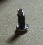
yes,pejinm said:...is this the idea?
thermo-shrinkable isolation around the screw...
and an insulating washer under the bolt head.
You can buy "top hat" insulators for this purpose.
Some packages are isolated around the hole to allow the use of a standard uninsulated bolt fixing.
Hi Andrew,
Thanks for reply!
But if I put isolation under bolt head, how should the colectors be conected to PCB?
Regards,
Miodrag
Thanks for reply!
But if I put isolation under bolt head, how should the colectors be conected to PCB?
Regards,
Miodrag
Hi pejinm!
Like quasi's image show or demonstrate, but use silicon insulating around the screw.If you don't have call me (cimni me).
Regards zeoN_Rider
Like quasi's image show or demonstrate, but use silicon insulating around the screw.If you don't have call me (cimni me).
Regards zeoN_Rider
Thanks Quasi,
Your image Quasi makes it clear, I recon it something like that...
Thanks Zeon,
I think I allready have some...
Regards,
Miodrag
Your image Quasi makes it clear, I recon it something like that...
Thanks Zeon,
I think I allready have some...
Regards,
Miodrag
Hi Guys,
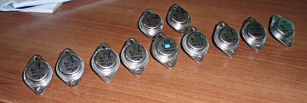
Earlier in my posts I mentioned, that I salvaged 13 of MJ21194 transistors, from the blown crown ce3000 amplifier.
All of them have some kind of markings on them. I think they come from manufacturing process.
My question is, do I have to take this markings seriously?
Is this mark the paired/unpaired devices?
Here is the photo...
Thanks in advance for reply!
Regards,
Miodrag
EDIT:
Also, the ones with "2" write on them have additional marking BM0147 in difference with the ones with "!" (BM0148)
Also two have dot marked with green pen like one in the middle...
Attachments
Hi,
I think you will need to measure them to see if there is a correlation between the markings and the test results.
I think you will need to measure them to see if there is a correlation between the markings and the test results.
- Status
- Not open for further replies.
- Home
- Amplifiers
- Solid State
- Brother of Quasi