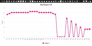
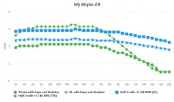
I finally got myself a descent signal generator and set about measuring my amp's frequency response.
It's quite flat up until about 3k, then rolls off towards the highs.
The gaps in the plot are due to I not having measured this frequencies but later decided to expand the scaling to flatten the roughly logarithmic curve.
It's quite flat up until about 3k, then rolls off towards the highs.
The gaps in the plot are due to I not having measured this frequencies but later decided to expand the scaling to flatten the roughly logarithmic curve.
Attachments
Tubby23,
Is that graph in Voltage units?
Or, is it in dB?
I seems like the high frequencies are rolling off too much and too soon.
Can you refer me to a Post in this thread that has the exact schematic of your amplifier build please?
Did you use a scope, or a DMM.
Most DMMs roll off at high frequencies.
Terminate your generator with the proper load (50 Ohms, 600 Ohms, etc.).
Then measure just the generator again by itself with your scope or DMM.
What is the result?
Lets solve this apparent problem for you.
Hi everybody greetings from Athens,Greece
I made up my choice about buying A9 built myself handcrafted. I have an issue with constant noise which starts as the amp is turned on and regardless the volume on both channels (also applies when volume is 0% but varies as i move the volume).Since it is common for both channels I believe that may come from rectifier which seems a bit crackling or the potentiometer
I made up my choice about buying A9 built myself handcrafted. I have an issue with constant noise which starts as the amp is turned on and regardless the volume on both channels (also applies when volume is 0% but varies as i move the volume).Since it is common for both channels I believe that may come from rectifier which seems a bit crackling or the potentiometer
I also reviewed 12AX7 as an alternate for 6N9P and found the following:
12AX7
in parallel mode is ok with 6.3v and 0.3A filament
Anode voltage Va 100 250 (V)
Grid voltage Vg -1 -2 (V)
Anode current 0,5 1,2 (mA)
Transconductance S 1,25 1,6 (mA/V)
AmplificationInternal µ 100 100
resistanceIa Ri 80 62,5 (kΩ)
Vh 6.3
Ah 0.3
Va 250
Vg -2.0
mAa 2.3
ra 44,000
gm 1.6
so in my understanding if I change only the pinout accordingly to 12ax7 I can replace the 6N9P's.
Any objections on that?
Tubby23,
Is that graph in Voltage units?
Or, is it in dB?
I seems like the high frequencies are rolling off too much and too soon.
Can you refer me to a Post in this thread that has the exact schematic of your amplifier build please?
Did you use a scope, or a DMM.
Most DMMs roll off at high frequencies.
Terminate your generator with the proper load (50 Ohms, 600 Ohms, etc.).
Then measure just the generator again by itself with your scope or DMM.
What is the result?
Lets solve this apparent problem for you.
Hi, sorry for the late reply.
It's in volts RMS.
I measured the values manually with one of those cheap little oscilloscope. It has osd readouts like any digital unit, sparing me from counting grid lines. LOL
I've performed further mods since posting this.
The rolloff is due to my cheap OPTs, possibly meant for guitar amps.
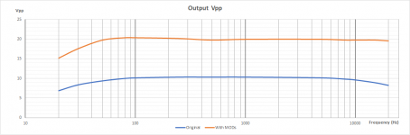
I've since introduced global NFB and step networks which have flattened the response curve and also cleared up severe ringing on my square waves.
1st pic is the improved frequency response in both UL and Triode modes and heavier GNFB.
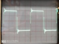
3rd pic is 1khz square wave taken at the 8 ohm tap in triode mode.
4th pic is an issue that developed in that one of the 6SL9's shunted cathodes came undone so the trace shows the difference in output between singular and parallel triodes.
5th pic is 1khz square wave in UL mode.
6th pic is the same before correction by step network and GNFB.
Attachments
-
![chart_maker_pro_1611708897690[1].jpg](/community/data/attachments/830/830125-e641775fc06bd5f67863b45af259c3be.jpg?hash=5kF3X8Br1f) chart_maker_pro_1611708897690[1].jpg93 KB · Views: 320
chart_maker_pro_1611708897690[1].jpg93 KB · Views: 320 -
![IMG_20210126_155641__01[1].jpg](/community/data/attachments/830/830144-d848c18ce2d69e61abfd9eadb5cb1c54.jpg?hash=2EjBjOLWnm) IMG_20210126_155641__01[1].jpg1 MB · Views: 306
IMG_20210126_155641__01[1].jpg1 MB · Views: 306 -
![IMG_20210126_162834[1].jpg](/community/data/attachments/830/830162-28bef0717bd4e7ed531fe38237b2b2dc.jpg?hash=KL7wcXvU5-) IMG_20210126_162834[1].jpg972.2 KB · Views: 304
IMG_20210126_162834[1].jpg972.2 KB · Views: 304 -
![IMG_20210126_171440[1].jpg](/community/data/attachments/830/830194-d714cbc49bf7552557886293581134b0.jpg?hash=1xTLxJv3VS) IMG_20210126_171440[1].jpg902.1 KB · Views: 125
IMG_20210126_171440[1].jpg902.1 KB · Views: 125 -
![IMG_20210126_181133[1].jpg](/community/data/attachments/830/830213-cd445b68816898163b0f7f1d2b1e6828.jpg?hash=zURbaIFomB) IMG_20210126_181133[1].jpg724.2 KB · Views: 124
IMG_20210126_181133[1].jpg724.2 KB · Views: 124 -
 IMG_20210119_131827.jpg680.5 KB · Views: 162
 -
 Boyuu A9.jpg242.4 KB · Views: 211
Last edited:
Has anybody thought of re-wiring the double triode pre-amp as CASCODE rather than parallel? Much better frequency response and lower Miller effect capacitance.
Hmm.. a sort-of Cascode - I was thinking more Anode of first triode connected to Cathode of second triode, second triode grid tied at 1/3 B+ with resistors then output from Anode of second triode to drive EL34. Second triode Anode connected to B+ via ~20k resistor.
Tubby23,
Is that graph in Voltage units?
Or, is it in dB?
I seems like the high frequencies are rolling off too much and too soon.
Can you refer me to a Post in this thread that has the exact schematic of your amplifier build please?
Did you use a scope, or a DMM.
Most DMMs roll off at high frequencies.
Terminate your generator with the proper load (50 Ohms, 600 Ohms, etc.).
Then measure just the generator again by itself with your scope or DMM.
What is the result?
Lets solve this apparent problem for you.
I'm intrigued by this suggestion.
I had no idea that it could be my generator rolling off itself for lack of a proper load.
Despite what my amp's response shows, it sounds fine to me with bright sounding highs - mind, my 50 year old ears are only good up to 13-14khz anyways..
Thanks for the suggestion - I'll try this later today.
Tubby23,
Post # 3's input stage is either an SRPP stage or a Mu Follower stage.
It is not a Cascode stage.
Can anybody tell me why they love the Cascode for Audio???
Cascode is great for use as an RF amplifier in a VHF TV tuner.
Cascode is great for use in a 30MHz IF amplifier for a ground search radar.
These are applications where the Bandwidth is much narrower than the carrier frequency (the carrier frequency is the center frequency).
Cascode is not so good for an audio amplifier.
632Hz is the geometric center frequency of 20Hz-20,000Hz.
The Bandwidth is much much wider than the center frequency (Exactly the opposite of what the cascode was invented for, and used in the above applications) . . .
Just my opinion.
Last edited:
There are a number of cited 'advantages' and of course, some 'disadvantages'.
First advantage is reduction in Miller effect, hence wider bandwith. This is particulalrly true where the A9 (and A10) doubles up the pre-amp triodes in parallel. Second advatage is the possibility of negative feedback within the pre-amp stage, providing reduction in distortion. Third advantage is that much higher gain is possible than the single triode stage.
Disadvantage is the output impedence can be quite high, so care has to be taken in the design.
The overall sound is apparently pentode like, not certain what that means...
Having previously owned an A10 (similar to A9, except uses 6N2P as triode), I always wondered why the double triode was wired in parallel.
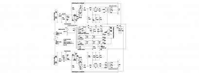
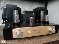
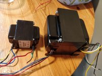
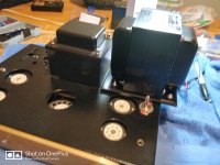
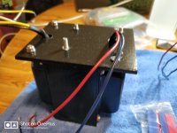
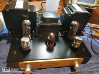
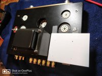
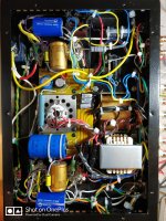
Here's my upgraded Boyuu A9, now with Hammond 1630sea output transformers and a reworked input stage, formerly parallel-tied, now Totempole/Half U as Merlin Blencowe calls it 6SL7s.
The old transformers I previously installed (not the OEM ones) had good bass but unacceptable high end rolloff and ringing. These are in another league.
In order to fit these monsters onto this tiny chassis I came up with the idea of using custom-made 100mm x 130mm x 6mm aluminium alloy plates to serve as brackets/shelves.
A nice side effect is because of the lower DC resistance of these, my HT has bumped up a little and my output tubes are now biased at 82% of max dissipation without the need to swap out the cathode resistor.
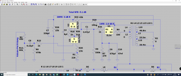
It has both global NFB (-3Db), tapped off the otherwise unused 16ohm lead and local NFB (-2.8Db) between the input and output plates, totaling at -5.Db. The Totempole input stage is unbypassed.
I was previously using a potential divider feeding 45v into all the heaters' artificial center taps for hum suppression but I had to rejig it for the Totempole because the max heater to cathode voltage permitted on an 6SL7 is 90v and there's now about 125v difference between the two cathodes of each input tube so I set the elevated voltage to about 65v, right in the middle.
Square wave testing reveals perfectly formed squares at 1khz, 2khz,..... up to about 10khz without the need of any step compensation apart from the 330pf cap strapped across the GNFB resistor of 15k setting the high end corner frequency at about 32khz., which I put in the design anyway.
The little amp has been completely transformed.
The previous harsh, guitar amp sound has been replaced by something much more musical and balanced.
Asked
Update:
I changed the input stage from parallel triodes in a bottle to what Merlin Blencowe refers to as the Half U, more commonly known as The Totem Pole Stage because the former is really optimized for low impedance loads while the latter is much more universal due to V2 working as a cathode follower which allows the stage to bias properly with less THD.
Before settling on the Totempole I briefly experimented with an SRPP but it wasn't suited to the high impedance 330k Rload of the power stage.
Changing that to Totempole just involved unsoldering the output coupling caps from the top of V2's cathode and attaching them to it's bottom (V1's anode).
The old transformers I previously installed (not the OEM ones) had good bass but unacceptable high end rolloff and ringing. These are in another league.
In order to fit these monsters onto this tiny chassis I came up with the idea of using custom-made 100mm x 130mm x 6mm aluminium alloy plates to serve as brackets/shelves.
A nice side effect is because of the lower DC resistance of these, my HT has bumped up a little and my output tubes are now biased at 82% of max dissipation without the need to swap out the cathode resistor.
It has both global NFB (-3Db), tapped off the otherwise unused 16ohm lead and local NFB (-2.8Db) between the input and output plates, totaling at -5.Db. The Totempole input stage is unbypassed.
I was previously using a potential divider feeding 45v into all the heaters' artificial center taps for hum suppression but I had to rejig it for the Totempole because the max heater to cathode voltage permitted on an 6SL7 is 90v and there's now about 125v difference between the two cathodes of each input tube so I set the elevated voltage to about 65v, right in the middle.
Square wave testing reveals perfectly formed squares at 1khz, 2khz,..... up to about 10khz without the need of any step compensation apart from the 330pf cap strapped across the GNFB resistor of 15k setting the high end corner frequency at about 32khz., which I put in the design anyway.
The little amp has been completely transformed.
The previous harsh, guitar amp sound has been replaced by something much more musical and balanced.
Asked
Update:
I changed the input stage from parallel triodes in a bottle to what Merlin Blencowe refers to as the Half U, more commonly known as The Totem Pole Stage because the former is really optimized for low impedance loads while the latter is much more universal due to V2 working as a cathode follower which allows the stage to bias properly with less THD.
Before settling on the Totempole I briefly experimented with an SRPP but it wasn't suited to the high impedance 330k Rload of the power stage.
Changing that to Totempole just involved unsoldering the output coupling caps from the top of V2's cathode and attaching them to it's bottom (V1's anode).
Attachments
-
 IMG_20210220_112340.jpg972.2 KB · Views: 339
 -
 IMG_20210222_110930.jpg936.8 KB · Views: 341
 -
 chart_maker_pro_1613966187829.jpg294.9 KB · Views: 315
 -
 IMG_20210213_155530.jpg983.4 KB · Views: 332
 -
 IMG_20210214_155027.jpg982.3 KB · Views: 321
 -
 IMG_20210215_115527.jpg851.5 KB · Views: 218
 -
 IMG_20210216_163624.jpg1,006.7 KB · Views: 232
 -
 IMG_20210213_162506.jpg988.4 KB · Views: 202
 -
 Screenshot (87).png183.1 KB · Views: 241
 -
 IMG_20210227_204615.jpg806.9 KB · Views: 244
Last edited:
Very nice!! I am going to have to re-draw your schematic. I think you should slap on some walnut side panels on to hide the transformers hanging over. The look would drive me crazy.
Is there any need for the .22uf cap at the input?
Protects the amp against any potential DC coming from the source and also reciprocally protects the source from a shorting input tube.
It also sets the low-end corner frequency to 1.54hz in conjunction with the 470k grid leak resistor.
- Home
- Amplifiers
- Tubes / Valves
- Boyuu EL34 A9 Tube Amp