Some DC voltage references would be useful. I have a pair of 1627SE's that need a project.
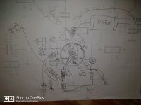
Here they are and the wiring diagram for the input tubes.
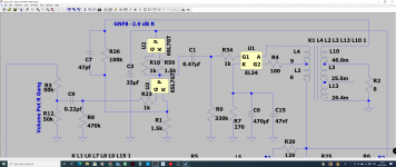
Note, I replaced the 5uf cap on V2's plate with a 33uf.
Attachments
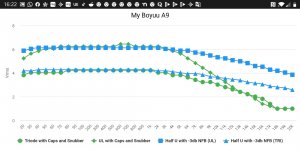
Decided to remove the -2.8Db loop between the input and power tube's plates.
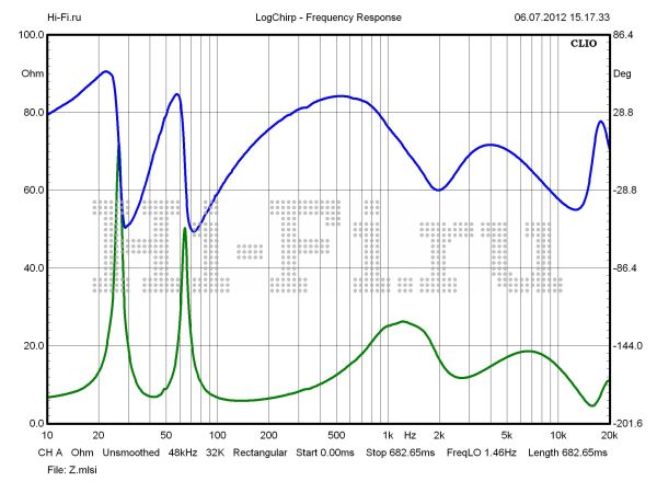
-3Db is plenty NFB for this amp, I think.
Curve not quite as flat but sounds livelier with a bit more power.
The signal now begins to clip with volume pot at around 4 o'clock whereas before i could turn it all the way without it clipping.
-3Db is plenty NFB for this amp, I think.
Curve not quite as flat but sounds livelier with a bit more power.
The signal now begins to clip with volume pot at around 4 o'clock whereas before i could turn it all the way without it clipping.
Attachments
Last bit of tweaking:
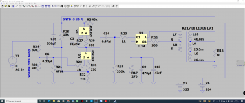
I reworked the DC coupled Totempole input tubes to get the biasing just right and simplified the GNFB arrangement since I chose not to bypass this stage.
I also decided the use the OEM PCB, albeit modded with a toggle switch instead of the clicky button.
I reworked the DC coupled Totempole input tubes to get the biasing just right and simplified the GNFB arrangement since I chose not to bypass this stage.
I also decided the use the OEM PCB, albeit modded with a toggle switch instead of the clicky button.
Attachments
-
 Screenshot (95).png185.1 KB · Views: 479
 -
![IMG_20210307_203835[1].jpg](/community/data/attachments/854/854743-a1b414b892ffcbcc14c5152bc04fbb9e.jpg?hash=obQUuJL_y8) IMG_20210307_203835[1].jpg493.4 KB · Views: 285
IMG_20210307_203835[1].jpg493.4 KB · Views: 285 -
![IMG_20210307_205757[1].jpg](/community/data/attachments/854/854772-c3f5fe96d66c23b17a7f4ca109840d1b.jpg?hash=w_X-ltZsI7) IMG_20210307_205757[1].jpg853.8 KB · Views: 258
IMG_20210307_205757[1].jpg853.8 KB · Views: 258 -
![IMG_20210307_212910[1].jpg](/community/data/attachments/854/854802-5d6a6e3a786aef3dc763912fa1d27ed8.jpg?hash=XWpuOnhq7z) IMG_20210307_212910[1].jpg1,004.6 KB · Views: 270
IMG_20210307_212910[1].jpg1,004.6 KB · Views: 270 -
![IMG_20210307_224115[1].jpg](/community/data/attachments/854/854824-f5203d74b9bcdb0c31d913da2468e70a.jpg?hash=9SA9dLm82w) IMG_20210307_224115[1].jpg974.6 KB · Views: 283
IMG_20210307_224115[1].jpg974.6 KB · Views: 283 -
![IMG_20210307_224123[1].jpg](/community/data/attachments/854/854851-e3e811a39382ca187ec4f3be58ab1d4b.jpg?hash=4-gRo5OCyh) IMG_20210307_224123[1].jpg984.3 KB · Views: 258
IMG_20210307_224123[1].jpg984.3 KB · Views: 258 -
![IMG_20210308_012037[1].jpg](/community/data/attachments/854/854871-5ce585870dfd8d0feba1299ee05528b5.jpg?hash=XOWFhw39jQ) IMG_20210308_012037[1].jpg271.6 KB · Views: 270
IMG_20210308_012037[1].jpg271.6 KB · Views: 270 -
![IMG_20210308_012055[1].jpg](/community/data/attachments/854/854890-c88d7662f3998d9d067674c27cd52140.jpg?hash=yI12YvOZjZ) IMG_20210308_012055[1].jpg316.9 KB · Views: 215
IMG_20210308_012055[1].jpg316.9 KB · Views: 215 -
![IMG_20210308_012107[1].jpg](/community/data/attachments/854/854901-d6bba8402d25b8666b587eb16ce183f9.jpg?hash=1ruoQC0luG) IMG_20210308_012107[1].jpg304 KB · Views: 236
IMG_20210308_012107[1].jpg304 KB · Views: 236
Looks a great result 🙂
What volatge B+ are you getting, and same question for top of totem pole?
What volatge B+ are you getting, and same question for top of totem pole?
Thanks!
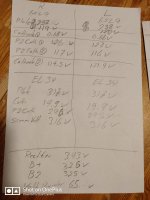
The last pic on my previous post has all the voltages listed��
Note that at the bottom of the list I wrote B2 as 307v but it was the first measurement I took and too soon after turning it on. Its 310v the same as the plates of the DC coupled cathode follower triode of the totem pole. The bottom common cathode triode plates are 154v.
Last edited:
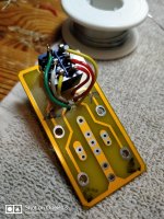
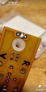
A nice little mod to the input selector board is to replace the cheap, dodgy clicky button with a DPST ON/ON switch.
Attachments
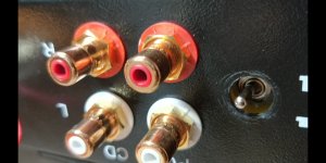
It would be far more convenient to have a selector switch at the front and replace on-off switch with off-on-volume. I appreciate that adds more noise source potential to incoming signals, however screened cable and copper tape shielding should minimise?
Thoughts...?
Thoughts...?
The chassis is a tiny off the shelf unit with a premade front fascia that's silkscreened.
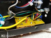
As you can see, it's crammed inside from previous mods.
I have only a DAC/preamp connected to one input anyway.
It is what it is and I'm fine with that.
But please, do tell me about copper shielding and how it's implemented.
I take it that it's grounded?
As you can see, it's crammed inside from previous mods.
I have only a DAC/preamp connected to one input anyway.
It is what it is and I'm fine with that.
But please, do tell me about copper shielding and how it's implemented.
I take it that it's grounded?
It would be far more convenient to have a selector switch at the front and replace on-off switch with off-on-volume. I appreciate that adds more noise source potential to incoming signals, however screened cable and copper tape shielding should minimise?
Thoughts...?
I put the selector (toggle) switch on the front panel on my amp builds. So-called line level input signals aren't very susceptible to interference.
It's not much of a challenge- just look at any receiver from the past 70 years or so to see how to implement a front panel switch.
Shielded cables tucked away from the AC power wiring in the 'corner' of the chassis will do the job - there's no need for extra copper shielding in my experience.
After saying all that, it's more difficult to modify an existing faceplate (and have it look good) vs making an unlabelled faceplate from scratch.
Due to the small and crammed chassis and to the forward mounted power switch, my left channel picks up the slightest of mains hum, only audible with ear up to left RP600M speaker and music paused.
All AC lines are wound and as removed as possible from the left channel circuit (which isn't saying much), apart from moving the power switch to the rear - which I won't do to the aforementioned faceplate issue, not to mention the little remaining real estate available at the back.
So I'm considering shielding options - something I can wrap around the nearby AC cabling and which must itself be grounded, right?
Last edited:
Tubby-
If you post some pics of the wiring you might get some suggestions for improvements or changes.
From the pic you posted, it looks like the AC power wiring is almost touching the input selector switch.
If you post some pics of the wiring you might get some suggestions for improvements or changes.
From the pic you posted, it looks like the AC power wiring is almost touching the input selector switch.
Tubby-
If you post some pics of the wiring you might get some suggestions for improvements or changes.
From the pic you posted, it looks like the AC power wiring is almost touching the input selector switch.
The green and white wires?
Those are the output transformer secondaries.
Last edited:
Which channel output transformer?
Seen from beneath and the PT at the bottom of the picture, the left side of the amp is the left channel, etc.
Last edited:
Hi All,
I haven't posted in a while but I've been reading these posts frequently.
I have a question for the experts in this group:
I've recently upgraded my speakers to the JBL Studios 580 speakers and the impedance is 6 ohms. Since the A9 amp has either 8 ohms or 4 ohms outputs, which ohm output should I use for this new speakers?
I'm assuming if I connect 6 ohms speakers to a 8 ohms output I will have more power output but it may damage and/or shortern the life of the amp. And if I connect 6 ohms speakers to a 4 ohms output the amp will run cooler but I'll have less power output. Is this correct?
JBL Studio 580
Thanks,
FLima
You may end up with higher distortion levels and inferior damping, but I wouldn't worry about the damage - it is highly unlikely.I'm assuming if I connect 6 ohms speakers to a 8 ohms output I will have more power output but it may damage and/or shortern the life of the amp.
The second part is correct, but the amp won't be "running cooler". Class A amps actually run cooler when they deliver more power to the load 🙂And if I connect 6 ohms speakers to a 4 ohms output the amp will run cooler but I'll have less power output.
Anyway, I would rather treat those speakers as 8 Ohm ones, but you should try both options and decide by ear.
Hey guys, what do you think of this amp? Is it worth buying assembled and using as is?
Also, A10 seems very close and has some raving reviews, but it's using a different tube in the input stage (6N2), any ideas how different these 2 amps are sound-wise?
Also, A10 seems very close and has some raving reviews, but it's using a different tube in the input stage (6N2), any ideas how different these 2 amps are sound-wise?
Last edited:
Hi Everyone................I'm hoping someone can help me. with a drawing maybe or a picture of Resistor R101 and R201 and the IN R and the IN L the value of Resistor and the connection to the pre amp valve.
- Home
- Amplifiers
- Tubes / Valves
- Boyuu EL34 A9 Tube Amp