Hi Allen
I missed your last post and posted onto the screen before I refreshed it. thank you that makes sense as the box was designed for a different woofer pair with a lower fs. The last post I did shows the woofer as pretty flat without the crossover both gated and raw. the tweeter looks like I should put the resistor and cap back in. I think if I am reading this correctly that the woofer is quite well behaved and a simpler crossover may be in order. the tweeter show a lot of dips and peaks. both show a slightly rising slope that would need to be addressed. I wonder if the peaks and valleys is the tweeter bouncing off the baffle, Do you think that a new box that fits the woofer pair is in order. would you build the box -then measure -then work on the crossover is that normal sequence? . If I am reading this correctly the woof and tweeters are way off on time alignment and almost look out of phase. so maybe a box with physical time alignment would be in order. thank you again
I missed your last post and posted onto the screen before I refreshed it. thank you that makes sense as the box was designed for a different woofer pair with a lower fs. The last post I did shows the woofer as pretty flat without the crossover both gated and raw. the tweeter looks like I should put the resistor and cap back in. I think if I am reading this correctly that the woofer is quite well behaved and a simpler crossover may be in order. the tweeter show a lot of dips and peaks. both show a slightly rising slope that would need to be addressed. I wonder if the peaks and valleys is the tweeter bouncing off the baffle, Do you think that a new box that fits the woofer pair is in order. would you build the box -then measure -then work on the crossover is that normal sequence? . If I am reading this correctly the woof and tweeters are way off on time alignment and almost look out of phase. so maybe a box with physical time alignment would be in order. thank you again
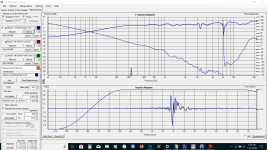
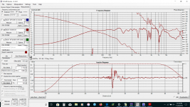
Your gated tweeter response has some comb filtering that I would guess relates to a 3 foot delayed reflection. Can you snip that one off? Sometimes it pays to close down the gating and wind it out slowly until something appears in the response that looks wrong, then you can give that some attention before stretching it longer.
Your woofer looks smooth for a 6.5", then again that could be due to your coarse amplitude resolution setting. There appears to be a rise in the top end. Why not compare it to the manufacturers specs? There will be a breakup region which is related to the woofer size and generally sets an upper limit.
Your woofer looks smooth for a 6.5", then again that could be due to your coarse amplitude resolution setting. There appears to be a rise in the top end. Why not compare it to the manufacturers specs? There will be a breakup region which is related to the woofer size and generally sets an upper limit.
Possibly, but to properly understand this it is necessary to take polar measurements. Until then it is best to stop using it at breakup (roughly 3,000Hz).I think if I am reading this correctly that the woofer is quite well behaved and a simpler crossover may be in order.
I didn't catch what the cap is doing but yes, a downward tilt to the response is not a bad thing.the tweeter looks like I should put the resistor and cap back in
I was talking about the outside of the box, I don't often find the inside to be very interesting.the box was designed for a different woofer pair with a lower fs.
This..
..but this wouldn't explain the deep nulls I mentioned in the last post. It would explain medium sized aberrations and delay times.I wonder if the peaks and valleys is the tweeter bouncing off the baffle,
No I wouldn't go that far just at the moment. I might consider some rounding of the corners, or simply a mock up of that effect using some damping material along the baffle.Do you think that a new box that fits the woofer pair is in order.
This is one way that will work, yes.would you build the box -then measure -then work on the crossover is that normal sequence?
The measurements still have the 23kHz ringing. Is you amplifier conditionally stable, did you build it yourself, do you use extra long cable runs, cut and twist your cables, is your mic buffered/preamp, do your in/out come from the same card, how do you derive your phantom power, is your card usb or internal, do you have your laptop plugged in when measuring?
However, I don't see that you have good phase data yet but it is getting close.
Your drivers are already close enough to cross. You'll find that crossing manipulates the phase and it should fall into line.If I am reading this correctly the woof and tweeters are way off on time alignment and almost look out of phase. so maybe a box with physical time alignment would be in order.
However, I don't see that you have good phase data yet but it is getting close.
thank you for taking so much time to help Allen I have learned a lot in the last few weeks.
Your woofer looks smooth for a 6.5", then again that could be due to your coarse amplitude resolution setting. There appears to be a rise in the top end. Why not compare it to the manufacturers specs? There will be a breakup region which is related to the woofer size and generally sets an upper limit Possibly, but to properly understand this it is necessary to take polar measurements. Until then it is best to stop using it at breakup (roughly 3,000Hz).
there is a breakup on the manufacturing specs I was surprised to not see it on my measurements. The current crossover is around 2100.
I didn't catch what the cap is doing but yes, a downward tilt to the response is not a bad thing.
The Thor Crossover has a resistor in series R2 and a cap C4 and resistorR3 in parallel to the tweeter that I removed. pdf attached
The measurements still have the 23kHz ringing. Is you amplifier conditionally stable, did you build it yourself,
My amp is suspect. I have an older Primare 2 channel amp A/B not the class C. Sounds good pretty good design terrible build quality I think it is a European design and Chinese build. I have had considerable issues with poor solder joints, blown fuses and issues with the amp shutting down and not coming back on. In fact when I played the music a little loud the other night the right channel of the amp went out and I have to pull the board and search again for a poor solder joint right now the amp is only a left channel amp.
the cables are 12 foot XLR the speaker cables are 5ft mit terminator from the 1990s the cable for the spl meter is just cheap rca and headphone cables.do you use extra long cable runs, cut and twist your cables, is your mic buffered/preamp,
dI am using an 2008 MacBook. the computer has a bad logic board about a week after the warranty ended and will only work when plugged in. It has been dropped and the monitor and trackpad do not work but the little bit that is left is still good😀o your in/out come from the same card, how do you derive your phantom power, is your card usb or internal, do you have your laptop plugged in when measuring?
the sound card is the mac sound card so the mic and the toslink are separate jacks but I believe the same soundcard.
thanks again Allen
Attachments
Ah yes, R3/C4 cut in around 6k to make sure that R2 can continue attenuating through the higher frequencies despite the rising impedance.The Thor Crossover has a resistor in series R2 and a cap C4 and resistorR3 in parallel to the tweeter that I removed. pdf attached
It can be a lot of work, chasing instability especially dependent on an intermittent. I don't remember the result of the loopback test but I would be doing it in stages, testing your computer.. plus amp etc. At each stage turn each device down and up systematically to demonstrate the settings to get the best S/N ratio.My amp is suspect.
I am also concerned about the look of the imported impulses.
Last edited:
Ah yes, R3/C4 cut in around 6k to make sure that R2 can continue attenuating through the higher frequencies despite the rising impedance.
Quote:
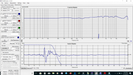
there is so much I don't know. I put everything back in. the gating is around 300 in auto
The no smoothing chart is also attached.
Quote:
there is so much I don't know. I put everything back in. the gating is around 300 in auto
The no smoothing chart is also attached.
Attachments
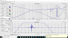
It's beginning to look like a speaker.
I would now slide back on the gate until the 7kHz null is affected, then zoom the impulse and continue to slide the gate back until all traces of that effect disappear. The distance between the start of the impulse and the start of the gate tells you where (in the room or on the speaker) to look for it.
I would now slide back on the gate until the 7kHz null is affected, then zoom the impulse and continue to slide the gate back until all traces of that effect disappear. The distance between the start of the impulse and the start of the gate tells you where (in the room or on the speaker) to look for it.
Hi thank you for the help Allen. That is a cool trick thank you. You are a Master speaker builder.
it look like about 6-7 cm if you are talking about the dashed line. Edge diffraction? there are allen bolts in the woofers and the heads stick out. it looks like removing the null also reduces the humps on either side of the null. I was ready to start changing resistors in the cross over. You think I would have learned to keep the soldering iron cold by now. After taking the components out and back in a couple of times. The woofers only have maybe 5 or 6 hours of run time on them so maybe I should let them break in awhile before I fire up the soldering iron again. it is starting to look like the Nextel woofer may work as a replacement for the Magnesium drivers I was really starting to regret my decision to make the change.
if it is edge diffraction should I relieve the baffle material to make a smaller baffle around the tweeter?
Does gating and moving the dashed line also apply to the large null at 150hz that looks like a room mode at 300cm?
I have the amp apart and hope to go thru the solder joints later today hopefully it will work again.
thank you again.
Attachments
Last edited:
Thanks 8, firstly let me clarify what I meant to say. The start of the gate (not the start of the gated region but the gate itself) is shown in your last plot at 2.5cm, directly below the 'p' of 'impulse response', and the end is closer to 6cm. (I noticed you have the 'gate' indicator at the bottom of the frequency response plot near 7k but since the impulse isn't lined up with zero, don't pay too much attention to that). You'll notice when the start of the gate slides back onto the end of the problem reflection, and when the end of the gate passes the start of the reflection. Then , using that reflection start point, add a few cm because your impulse started early.
Also, this is a round trip distance. If sound moves across the baffle for 5cm, then detours toward the mic (as it does with diffraction) the total difference will greater. in this case, 5.12cm
Also, this is a round trip distance. If sound moves across the baffle for 5cm, then detours toward the mic (as it does with diffraction) the total difference will greater. in this case, 5.12cm
Last edited:
Dome tweeters have a faceplate that represents a plane, and were designed to radiate at 180 degrees along a baffle. The baffle is preventing diffraction. You want to stop the sound from seeing the edges. You can round them, provided the roundover is large enough to assist at the frequencies you need it to.if it is edge diffraction should I relieve the baffle material to make a smaller baffle around the tweeter?
I wouldn't suspect the woofer at these higher frequencies unless its frontage may upset the tweeter.
I think this is beyond your clear zone, so no. because it will change when you move the speaker.Does gating and moving the dashed line also apply to the large null at 150hz that looks like a room mode at 300cm?
Thank you Allen
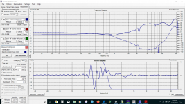
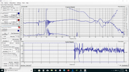
I worked on the amp most of the available time yesterday but could not get the right side to work . so today I installed the old Marantz and that means no XlR cables and a pretty rough speaker wire setup. I also removed the bolts that are close to the tweeter. Here is the new chart.
Looks like the diffraction is the edge of the cabinet. I am not sure why the treble is so different really dropped with the Marantz vs the primare. thank you again for your help.
Attachments

I again removed r3 and C4 it looks like the edge is affecting 4 k and 7k at least there is a flat response on the raw measurement from 500 t0 6000 or there abouts. I am not sure if I should spend anymore time on the crossover. or focus on room placement and port length. Or if I should start on a new smaller box. these speakers only have a FS of 40 and call for 24 lt and from what I have read it fs may be closer to 55 the mags are fs of 34 and call for 30 lt
I have been doing a lot of reading on trying to design ones own speakers and the overwhelming consensus is to build an established design so I woke up this morning thinking about putting the corroded mags back in and seeing if I could send the drivers back. but after spending the morning working on them and getting the flat frequency response I think I would like to make these work. the Mag drivers may not last long in my environment.
I have been doing a lot of reading on trying to design ones own speakers and the overwhelming consensus is to build an established design so I woke up this morning thinking about putting the corroded mags back in and seeing if I could send the drivers back. but after spending the morning working on them and getting the flat frequency response I think I would like to make these work. the Mag drivers may not last long in my environment.
Attachments


Probably the main reason people suggest using an established design is the crossover, which is also used to set the tone of the speaker. What you have isn't a bad place to start I guess, as it is close enough that you can continue to make modifications as you have been doing.
The bass is room dependent. In the last plot you posted, virtually everything below 200Hz is under its influence. Getting this right first is worthwhile, and since music is rich with harmonics it should improve the quality of the lower bass. You may even find a place that boosts/extends it.
The bass is room dependent. In the last plot you posted, virtually everything below 200Hz is under its influence. Getting this right first is worthwhile, and since music is rich with harmonics it should improve the quality of the lower bass. You may even find a place that boosts/extends it.
thank you Allen
I have to keep working on the measurement system I removed R3 and C4 from the right speaker measured and got a very different FR than the left speaker moved back and measured the left it was similar to the right and it was very different than the one posted above even thou absolutely nothing changed on the speaker or mic placement. I have to get some other work done but getting repeatable measurements will be my next priority. I am chasing my tail if I cannot get the measurements to repeat.
A question for future reference - will moving the tweeter from the center to one side help the 7k null?
thank you Allen
Assuming it is the result of a cabinet edge, maybe you could put something absorbent on your baffle to confirm this. Rearranging the tweeter will rearrange the diffraction, and this can give the appearance of an improvement from some angles.
Thanks Allen As soon as I figure out how to get accurate or at least consistent measurements I will try it. I tried to get the windows laptop to work with holms and I can get music to play ok but the measurement sweep is very very quiet. barely audible. I actually made some wool felt pads to go around the twitter so I can put them back on and try it.
About inconsistencies. Sometime they just happen and are an internal issue, but they can come from the unexpected. I recently took a measurement that looked surprisingly good, then made a change for comparison and it looked much worse, ie beyond what it should have been and it turns out I was skating very close to the limit of the input and there is a 5-10dB range where the input is smoothly clipped toward max. Another common one I find is making sure I've lined up the impulses correctly, eg clipping the start slightly is not good.
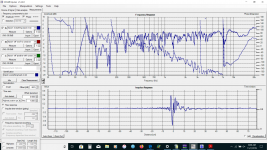
there really has to be something wrong with the way I am set up I finally got the laptop to work with holms but I am getting a weird worbleing sound at the top end of the FR and a chart that looks like the one attached . I have to review the settings and see what is happening again entirely different than the REW measurements. The speakers sound ok there is no noticeable missing treble when listening to music.
Attachments
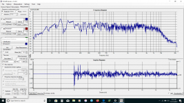
If you are confident of better results with REW then maybe that's what counts. What version of windows is that, I know that windows sound has reduced in quality in the last 10 years (something Holm counted on).
Anyway I've begun using REW as a secondary measure on another (non windows) system. Unless I'm doing it wrong I find its impulse is more difficult to line up and its windowing setup is more complicated, especially when I don't use the timing channel. However good results is what counts.
I've heard that in the past, don't remember any issues with it. You could restart the stream (first tab), and restarting windows sometimes helps with issues.a weird worbleing sound
Anyway I've begun using REW as a secondary measure on another (non windows) system. Unless I'm doing it wrong I find its impulse is more difficult to line up and its windowing setup is more complicated, especially when I don't use the timing channel. However good results is what counts.
Last edited:
- Home
- Loudspeakers
- Multi-Way
- Box port or crossover dippity do