AndrewT:
I had it playing music with the volume all the way up yesterday for hours with no problems, but logically, right now it is in an open case. I will get CPU type heatsinks for the case, this is going to slow me down because I will have to choose them and the enclosure accordingly to each other's dimensions.
But, again, I thank you and Pacificblue very much for your help, this thing sounds amazing... And no, I'm not exaggerating...
Now I need help with the additional, supposedly 15 volt secondaries in the transformer. I am not using them for now because I didn't install the speaker protection board and the input selector board, but the idea is to use them in the final amplifier installed in the enclosure.
According to the sellers of these things, they can be powered with 12 to 15 volts AC, but nothing over, can you please provide more details on how to reduce the 16.4 volts I am getting out of those two secondaries to, let's say, 14 volts...?
Question number two, the input selector board has 4 LED's to indicate the input selected, there is a picture of it and its schematic in post #17 in this thread. Can I solder wired LED's in parallel with the ones already on the board so I can install them in the enclosure's front panel, or do I have to desolder the ones in the board and replace them with the wired ones?. What I mean with "wired LED's" is some LED's they have at Radio Shack, they come with a plastic ring to make them panel mount type and two wires about 12 inches long.
Yes, AndrewT, there is a picture on post #140 that shows the two amps with their heatsinks attached.
I will be posting pictures in a while of the whole thing installed and working. I am pretty sure you guys are going to have a fit as soon as you see all the wires, but I am telling you, no hum, no noises of any kind...
The 12Vac or 15Vac is the rated transformer voltage.
All transformers change output voltage as the current load is changed.
16.5Vac, when measured open circuit, is quite normal for a 15Vac transformer.
Connect up as described in the literature.
The sinks are small, but I would not have expected them to be burning hot.
Doubling the size, or dissipation capability will certainly reduce the operating temperature.
But, maybe there is another problem. Can you check for oscillation? How hot is the Zobel resistor? Is the Zobel resistor still measuring 10r?
Regarding the heatsinks, I don't know if this is really important, I used Dell part number UP755, Powerstrate Xtreme thermal interface pads made by Loctite between the heatsinks and the LM3886's. I use this product a lot when replacing motherboards in laptops but I didn't know it was so good, CPU's don't get as hot as these heatsinks I have, these thermal pads seem to be doing their job pretty well...
AndrewT, how do you want me to measure the Zobel resistor?. With the amp ON playing music, or with the amp OFF?.
amp off and disconnected from the mains.
Set DMM to the lowest resistance range.
Does the 10r measure the same as it did before you soldered it in?
To check temperature of the resistor you do need the amp to be powering a speaker.
Set DMM to the lowest resistance range.
Does the 10r measure the same as it did before you soldered it in?
To check temperature of the resistor you do need the amp to be powering a speaker.
I can check the resistance, but I can't check temperature, my DMM doesn't have that feature.
Anyhow, the 10R resistors on the PCBs measure 10.2 Ohms each, the ones in the + speaker cable together with the inductor measure 0.8 Ohms each...
Anyhow, the 10R resistors on the PCBs measure 10.2 Ohms each, the ones in the + speaker cable together with the inductor measure 0.8 Ohms each...
Hey Aguilabrava - I forgot to subscribe to your thread here so I've missed some of the action. 😀 I got caught up this morning reading the posts. Sounds like you've been busy lately. I'll be sure to keep reading and injecting where I can. You're tackling more than I am with this build, but it's good you started with bare kits, so replacements parts was easier!
Hey, Redjr, how are you?.
Yes, I've been pretty busy, I am happy because I was very anxious to test the amps and I finally could. I am more than satisfied with the results, the sound is incredible, I can't thank AndrewT and Pacificblue enough for their help.
If you plan to do any modifications to your boards, read the previous posts for component values, if you go back you will see, for example, that the 1.5uH inductor I used in the Thiele network by the + output speaker cable is not the ideal as indicated by Pacificblue and AndrewT, again, the sound that these amps produce couldn't be better, but in your case I would get the best option which is described in previous posts by both, AndrewT and Pacificblue.
I'm not building a 3886 based amp, but a class AB based on the 4702 chip. Thread here. I have been reading other threads, but got caught up in my DAC build. Since I bought my modules already assembled, my first pass will be just to assemble everything together to see how it works and sounds. I'm sure I'll discover a few things along the way. 😀 From there, I'll decide what mods or 'improvements' are worth the effort and have a noticeable impact on the sound. For me, that's my preferred approach. However, my assembly techniques will easily allow for mods or swapping out modules.
Your build sounds like is coming along nicely.
Your build sounds like is coming along nicely.
The transformer gives 16,4 VAC. You will need 12..15 VDC. So first you need a rectifier and a smoothing cap just like for your amp, only smaller. You will get something like 23 VDC. There are several ways to bring that voltage down to the value you need.can you please provide more details on how to reduce the 16.4 volts I am getting out of those two secondaries to, let's say, 14 volts...?
One is easy to build, but a little more elaborate to configure. You need three components, a series resistor, and a Zener diode and a capacitor parallel to the load. To configure it you need to know the highest and the lowest current that will flow into the load. Zener power supply
Another needs a few more components, A voltage regulator, e.g. 7812 for 12 V or 7815 for 15 V, two 100 nF ceramic caps as close as possible to the in- and output and a few bigger smoothing caps in parallel to the 100 nF. Depending on the amount of voltage you have to drop and the current that will flow you may need a heatsink on the 7812 or use a series resistor before it. regulated power supply
There is a section on power supplies on the Forum.
There are 1k resistors in series to the LEDs. So if you solder LEDs in parallel to the existing ones, both will be half as bright. If that is bright enough for you, sot. It not, solder LEDs with their own 1k series resistors in parallel to the existing LEDs and series resistors.Can I solder wired LED's in parallel with the ones already on the board so I can install them in the enclosure's front panel, or do I have to desolder the ones in the board and replace them with the wired ones?
There is no provision for an output Zobel.
Use the locations of R1 and the speaker terminal to fit an R+C Zobel.
R1=2r0 to 10r
Speaker terminal=47nF to 220nF.
Add the other half of the Thiele Output Network, the R//L, off the PCB. R=2r0 to 10r L=0.5uH to 1.5uH
Insert a thick copper wire in this pad first, The top end of R1, nearest the output PIN.
Attach R1 to the copper wire.
Take the speaker output from the top end of R1. Attach the speaker wire to the copper wire. I suggest you fit the speaker wire on the bottom side.
You could bend over the top side of the copper wire to lie on top of the output PIN. Solder this connection. But fit a temporary tab heatsink next to the package since quite a bit of heat will try to travel along this PIN during soldering.
I'm also considering to use the Thiele network in my XY kit, but have some questions about it
- What is the minimal wattage for the Zobel resistor?
- I have some WIMA MKP10 100nf (400V) capacitors left. Are the OK to use for the Zobel?
- Where to put the other half of the Thiele network? close to amp board or close to the speaker connector in the chassis?
- What is the minimal wattage for the resistor in the second part of the Thiele network?
- So the saturation current for the inductor should at least be 4-5 A. Such inductors are hard to find. where can I buy them? Or can I make them easily myself.
- What is the use of the copper wire on the top side that is to be soldered onto the output PIN? Is this nessecary?
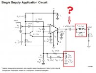
In the attachment you'll find a diagram from National Semiconductor. Are the components with the red lines around them by any chance the Thiele Network?
There is also a large capacitor in the output line. Why?
For a diy inductor:
Diam. 8 mm
15 turns
1.5 mm copper
= 0.7 uH
Diam. 6.5 mm
13 turns
1.5 mm copper
= 0.45 uH
Diam. 13 mm
15 turns
1.5 mm copper
= 1.48 uH
How much space should there be between each winding?
I found this diy manual for inductors. It should not be that hard to make one or two myself, right? But how to measure if I got it right?
Attachments
Last edited:
It will work with a normal metal film 600 mW unless you don't check the amp with 200 kHz att full power.
The coil should look like this:
http://sjostromaudio.com/hifi_pics/hifi_100pr/qrp01r0_overview.jpg
http://sjostromaudio.com/hifi_pics/hifi_100pr/qrp02r0_overview.jpg
The coil should look like this:
http://sjostromaudio.com/hifi_pics/hifi_100pr/qrp01r0_overview.jpg
http://sjostromaudio.com/hifi_pics/hifi_100pr/qrp02r0_overview.jpg
Last edited:
It will work with a normal metal film 600 mW unless you don't check the amp with 200 kHz att full power.
The coil should look like this:
http://sjostromaudio.com/hifi_pics/hifi_100pr/qrp01r0_overview.jpg
http://sjostromaudio.com/hifi_pics/hifi_100pr/qrp02r0_overview.jpg
So the wires of each winding are allowed to touch each other?
The turns of the output inductor use enameled copper wire.
You will have two layers of that enamel insulation between each touching pair of copper turns. What's the problem?
Yes, the 4 components inside the red outlines are the Thiele Network.
The amplifier should never become unstable. The amplifier should never see a significant RF signal after the input filter.
The resistors in the Thiele Network should never get hot.
Buy a few 500g reels of enameled copper wire. 0.6mm is great for adding low current windings to an existing toroid transformer.
1mm, 1.2mm, 1.4mm & 1.6mm are good to have in stock, if you intend doing a lot of amplifier building.
Last edited:
The turns of the output inductor use enameled copper wire.
You will have two layers of that enamel insulation between each touching pair of copper turns. What's the problem?
I never realised that the copper wire was enameled.
So 600 mw for the resistors should be enough then?Yes, the 4 components inside the red outlines are the Thiele Network.
The amplifier should never become unstable. The amplifier should never see a significant RF signal after the input filter.
The resistors in the Thiele Network should never get hot.
The capacitor is also for stabillizing the amplifier?
I'm not intending to build a lot of amplifiers, but I will probably be able to buy a smaller amount of enameled copper wire somewhere.Buy a few 500g reels of enameled copper wire. 0.6mm is great for adding low current windings to an existing toroid transformer.
1mm, 1.2mm, 1.4mm & 1.6mm are good to have in stock, if you intend doing a lot of amplifier building.
- Home
- Amplifiers
- Chip Amps
- Bought a XY LM3886 Kit