Bonsai, other than appearance, is there any reason to get the 10 mmm front panel over the 3mm ?
I have all of my passives mounted and have just done my first power up test. Luckily I’m getting about -15.007v and +15.052v at the test points. Huzza! Thanks for the help getting this far. My raw voltages are a bit high at 16v and 31v rather than the suggested 10 and 25v +/- 3vdc. I’m wondering if I should be worried about these input voltages being a bit high or if the regulators will be able to handle the difference.
I’m thinking that this must just be my local voltage and possibly the transformer that I’m using. I’m in Canada where line voltage is 120VAC and I wasn’t able to get RS to ship here so for a transformer I have a YHDC PTC3.2 which is rated at 2x 115v in 15v out.
I also noticed that C55, which is mounted on the bottom of the board, has a +symbol printed beside one mounting hole on the top side of the board and there is also a + symbol printed beside the other lead on the bottom of the board. Which is the proper orientation for this electrolytic cap?
Steve, I am away this weekend. I’ll come back to you on Monday night with clarification. Cheers
Hello Steve
1. Soldermask issue with cap. Please follow the BOTTOM solder mask and ignore the top. I will add this to the errata and update the audioXpress supplementary data pack.
Boards shipped after May 22 have this issue corrected.
2. Transformer Voltages.
These voltages are a bit high, but best thing to do is build it and see how hot the regulators run. The current draw is low, so I think you should be ok. If worst comes to worst, you can always attach some heatsinks.
Thanks. I’m feeling pretty confident to go on to the next step now. I guess I was most worried about the higher voltages before the regulators. I’ll follow up with what kind of temperatures I get once it’s complete and running.
I noticed that in the (slightly blurry) image in the build instructions which shows where to check voltages the positive sign for that capacitor is a close match to the mask on the bottom of the board, so I was guessing that the orientation marked on the bottom was correct.
I noticed that in the (slightly blurry) image in the build instructions which shows where to check voltages the positive sign for that capacitor is a close match to the mask on the bottom of the board, so I was guessing that the orientation marked on the bottom was correct.
Yes. The bottom orientation is correct.
(audioXPress supplementary data pack has been updated - the errata sheet is the first page of the Excel BOM spread sheet)
(audioXPress supplementary data pack has been updated - the errata sheet is the first page of the Excel BOM spread sheet)
Hi Bonsai, I followed the old BOM and ordered 3 of the LM4562. But the latest update is for 4 as per the PCB. I placed another Mouser order for this and the remaining resistors. Mouser then let me down, and the delivery for these is now out to October. I looked around and the cheapest option is RS who stock the MA version but not the MAX. The MA version appears the same device. Just the shipping packaging. So this could be an option for others..
There are 4 LM4562’s on the board - 2 for front end regulators and 2 for the hybrid EQ stage. Apologies if the original BOM only showed 3.
There is a world wide semiconductor shortage at the moment so expect so me long shipping times
🙂
There is a world wide semiconductor shortage at the moment so expect so me long shipping times
🙂
I’m wondering what point in the build and testing procedures I should be adding the switches. I understand that I want to leave the dip-switches and push button as late as possible so that I don’t contaminate the contacts when I’m washing off flux, but should they be installed when I’m checking voltages with the OPA1641 and LM4562 installed.
Also, is there a diagram somewhere of how to wire the rumble filter switch and at what point in testing should I add it? I feel like I saw a diagram somewhere but I don’t see it in the build instructions package or this thread.
If anyone is having trouble getting LSK398 shipped to them I’m in a Canada and ordered some from Trendsetter Electronics in Georgetown Texas. When I asked nicely they shipped them to me via USPS rather than FedEx which I appreciated and avoided an additional fee. I have a couple of extra LSK389A if someone in Canada is looking for these chips. I don’t know if/how the A grade chips would work but that’s what I will have left over.
Steve, you will be able to measure all the DC test voltages without the DIP switches fitted - ie +-5V, +10V and then on the main PSU test points +25V and +10 V.
On the LM4562 opamp positions measure +15V on pin 8 and -15 V on pin 4. On the OPA1641 positions, measure +15 V on pin 7 and -15 V on pin 4.
If all these voltages are ok, you are good to go.
The rumble switch wiring is on the X-Altra MC/MM page at hifisonix.com here http://hifisonix.com/wordpress/wp-content/uploads/2021/04/Filter-switch-wiring.pdf and also in the download pack from audioXPress here https://audioxpress.com/files/attachment/2737
Last edited:
I misplaced my 2 pcs. of 80-C0805X473F3GECAUT (1% .047uF C0G caps). Mouser and DigiKey have a long lead time for these parts. In Kemet's datasheet, X indicates it is flexible version. Andrew, any reason why the non-flexible C version won't work on the board? There are plenty in stock at Mouser.
Steve, you will be able to measure all the DC test voltages without the DIP switches fitted - ie +-5V, +10V and then on the main PSU test points +25V and +10 V.
On the LM4562 opamp positions measure +15V on pin 8 and -15 V on pin 4. On the OPA1641 positions, measure +15 V on pin 7 and -15 V on pin 4.
If all these voltages are ok, you are good to go.
Thank you. I was wondering why the rumble switch is a 4pole, but that makes perfect sense not that I see it.
I have +15 and -15 input at the correct pins at all of the LM4562 and OPA1642 so I've mounted them and the OPA2189 but unfortunately I'm only getting -5v in the proper locations now that i have them mounted. My measurements are low where i should have 10v and +5v. My raw ~10v has also dropped down to about 7.5v. I guess I'll have a look at the diagrams for these chips and check the output voltages of each one tomorrow.

Attachments
Apologies - the regulated +-5 and +10 won’t be present without the LM4562’s.
If you have +-15 at all the opamp pins, that’s a good sign. You must have +-5 and +10 and they have to be ultra clean with zero noise (ripple etc). It seems your +10 V are not regulating. Can you check that all the caps are the right way around - if not they will load the opamp outputs and pull the output down.
Can you measure the voltage drop across each of the 7815 regs. Across input to output you want at least >4V and preferably a little higher to ensure you get no ripple bleed through. If you have a scope to hand, you can check that output is clean as well - ie no ripple and in regulation.
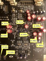
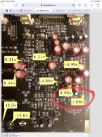
Steve, can you check the voltages across the 5.6 k divider string (ringed in the attached pic). Starting from +15 you should get +15, +10 and then +5. From the -15 V rail, you should get -15, -10 and then -5. All voltages wrt 0 V.
Each 10 and 5 V rail is decoupled with a cap - if any of these are the wrong way around or leaking, it will pull the voltages down. Your -5 V rail looks good (so -10 should be ok by implication) but your +5 and +10 don’t look good - check that the caps are all the right way around and/or there is not a problem with the resistors.
Each 10 and 5 V rail is decoupled with a cap - if any of these are the wrong way around or leaking, it will pull the voltages down. Your -5 V rail looks good (so -10 should be ok by implication) but your +5 and +10 don’t look good - check that the caps are all the right way around and/or there is not a problem with the resistors.
Attachments
Yes, it looks like something is pulling down the +5v to 1.8v. When i measure across the 5.6k resistors the negative values look good (0, -5, -10, -15), but the positive values are off (+15, +8.2ish, +1.8, 0). I popped the 5.6k resistors off, tested them, switched the positive and negative ones and put them back on with no change of results. They all tested good and I haven't found a bad or reversed capacitor yet. I'm mainly looking at C12, C14, C15, C19, and C20 (as well anything near by that i can think of).
Are U4 and U5 paralleled? I'm now wondering why I'm getting -5v at pin 3 but +1.8v at pin 5 of both of these LM4562's. Any suggestions on other places to look for what's pulling down the +5 would be most appreciated.
Are U4 and U5 paralleled? I'm now wondering why I'm getting -5v at pin 3 but +1.8v at pin 5 of both of these LM4562's. Any suggestions on other places to look for what's pulling down the +5 would be most appreciated.
U4 and U5 (I assume you mean U3 since U5 is the MC gain setting switch for the right channel) are not paralleled. U4 opamp 2 and U 3 opamp 2 are the +5 V regulators and op amp 1 in the same devices are the -5 V regulators. The regulators for each channel are completely separate.
To move forward,
1. check that the voltages on pins 5 and 6 on U3 and pins 5 and 6 on U4 are equal.
2. Check that pins 2 and 3 on U26 are equal to within 1 mV and the same in U19
3. If the voltages are the same on the pins on each opamp to within 1 mV, the opamps are probably ok and the issue then is that the + side of the divider chain is being loaded down by the caps. To check this remove C15 and then check the voltages again. If still wrong, remove C30.
Hope this helps - let me know how it goes.
Last edited:
Success!
Thank you four your patience and kind support. Somehow I had a poor connection to the pad of pin 7 of U4. I was able to rework it and now have a good +5 and +10v.
I was a bit confused about what U3 and U4 were doing in the circuit and why I wasn't seeing +5 and +10 anywhere if both of these are producing separate positive and negative 10v and 5v for each channel. I had been looking at Figure 5 of Part 1 of the AudioXpress article and trying to figure out why i seem to have the same fault on both U3 and U4 though. I guess that the +5 and -5 from U4 are fed in to pins 5 and 3 of U3.
(Sorry. Yes, I meant U3 and U4 rather than U4 and U5 in my last post.)
Attachments

It is a bit confusing because the reference voltages for the regulators (U3 and U5) come off the same divider network (right next to U3 in Fig 5 part 1) - so if the reference chain has a problem and opamps are working ok they will show a similar output voltages so it looks like they are in parallel.
Anyway - good that you solved it - you voltages all look good!
Anyway - good that you solved it - you voltages all look good!
Last edited:
Post Assembly Test.
Hi Bonsai.
I have assembled and I have a couple of questions. Would post an image but not sure how to do that.
Both my LC & RC 10V rails are slightly low at 9.90 & 9.91V respectively.
My Left channel input offset is 41.7mv is higher than specified 🙁 (right is ok at 6.0mv). Thought might be a leaky cap? Yes I reversed C9&25 before assembly. So not that.
Do you think either of these going to cause a problem before I start swopping Caps around?
For Ref. Measurements taken with uncalibrated Fluke DMM:
+15V 15.06V, -15V -15.06V
10v low noise 10.03V LC 10V 9.91V RC 10V 9.90V
LC +5 5.021V, -5 5.018V RC +5 5.021, -5 5.019
R61 2.795V R82 2.778V
Collector Voltages Q1 -1.506V Q2 1.508V Q3 1.461V Q4 -1.459
Input offset L 41.7mv, R 6.0mv
- Home
- Source & Line
- Analogue Source
- Bonsai’s X-Altra MC/MM Phono Preamp