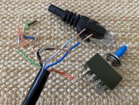
In wiring the Filter T/O Switch, I thought a good option was to use some CAT6 cable (CAT5 ok). It's already color coded, twisted and sheathed (making it easy to tuck into the side panel groove to keep distance from the power supply).
A 26G wire stripper makes the prep easy. Since there are 4 pair and only 3 pair are used, I doubled-up the wires going to pin 2 for each channel.
A 26G wire stripper makes the prep easy. Since there are 4 pair and only 3 pair are used, I doubled-up the wires going to pin 2 for each channel.
Attachments
Last edited:
I could not find an 18VAC transformer and went with a similarly powered 15VAC. The voltages seem okay. While the 25V TP next to the transformer measures 20V, the regulators are putting out ±15VDC.
At all ICs, the proper legs measure + or -15V. The -5V TPs are correct. So far so good.
But at the +5V and +10V TPs, all measure 0V.
I've tripled checked the cap polarities and verified against those in your video. I also re-checked and re-soldered all IC legs.
At this point, I'm suspicious of the PS ladder immediately adjacent to the MM LED. [BTW, the MM LED correctly lights up when the MM is switched selected, but the MC LED, when switched to MC, does not light up (anode is properly wired per PCB mask).]
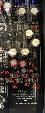
I've not seen any detailed schematics of the PS ladder but the voltages seem strange to me. Attached is a photo with some of my measurements.
R16 measures +15V and -15V on the mirror image of R13. While R14-R17 step down the -15V to -10V and -5V, the other side only measures 0V on both sides of R15 and R18.
C14, which is on the +side of the ladder (and so I expected +voltages), measures -5V on the negative leg and 0V on the positive leg. I removed C14 for more testing, and this is why it is not present in the attached photo.
Any suggestions? The proble seems similar to that of masoste from post 152 on p16, but checking ICs did not fix the problem.
***
One other question, there are 2 set of SMD pads next to the MC input. These are not present in the schematic. I've left un-populated.
At all ICs, the proper legs measure + or -15V. The -5V TPs are correct. So far so good.
But at the +5V and +10V TPs, all measure 0V.
I've tripled checked the cap polarities and verified against those in your video. I also re-checked and re-soldered all IC legs.
At this point, I'm suspicious of the PS ladder immediately adjacent to the MM LED. [BTW, the MM LED correctly lights up when the MM is switched selected, but the MC LED, when switched to MC, does not light up (anode is properly wired per PCB mask).]
I've not seen any detailed schematics of the PS ladder but the voltages seem strange to me. Attached is a photo with some of my measurements.
R16 measures +15V and -15V on the mirror image of R13. While R14-R17 step down the -15V to -10V and -5V, the other side only measures 0V on both sides of R15 and R18.
C14, which is on the +side of the ladder (and so I expected +voltages), measures -5V on the negative leg and 0V on the positive leg. I removed C14 for more testing, and this is why it is not present in the attached photo.
Any suggestions? The proble seems similar to that of masoste from post 152 on p16, but checking ICs did not fix the problem.
***
One other question, there are 2 set of SMD pads next to the MC input. These are not present in the schematic. I've left un-populated.
Attachments
I found Bonsai’s suggestion of testing the voltages at each of the pins of U3 then U4 to be the most helpful in my case. Because I had an issue with a solder point on a pin on U3 I wasn’t getting the right outputs from either U3 or U4. I think that U3 does the negative rail (if I remember correctly) which looks like you have working, so I’d check and see what you have at the pins of U4. I remember that I ended up looking at the diagram of the spec sheet for the LM4562 to confirm that I was testing the correct pins.
This correct. I will come back later today with some more detailed voltage readings that you can take across the 5.6k divider chain.
Note that if any of these 5.6 k resistors is missing solder on a pad, all your auxiliary voltages (ie +-5 V and +10 V) will be wrong. Also make sure your decoupling caps off the divider chain are the correct way around because if not, this will pull the voltages down as the cap (electrolytic) goes leaky.
Note that if any of these 5.6 k resistors is missing solder on a pad, all your auxiliary voltages (ie +-5 V and +10 V) will be wrong. Also make sure your decoupling caps off the divider chain are the correct way around because if not, this will pull the voltages down as the cap (electrolytic) goes leaky.
Please measure the voltages at pin 5 and pin 3 on U3 and U4
On pin 5 you should get +5V and on pin 3 -5 V.
To check that U3 and U4 are working, the voltages on pins 3 and 5 should be accurately replicated on pins 1 and 7 respectively - this applies whether the 5.6 k divider chain is working correctly or not.
To check the diver chain which feeds U3 and U4 check the following:-
At the junction of R15 and R16 you should read +10V and at the junction of R13 and R14 -10 V
If these voltages are not correct, check that all the 5.6 k resistors are soldered down correctly. Make sure C14, C15 and C30 are correctly oriented wrt polarity.
The voltages on the image I uploaded yesterday are the same as I measure today: no +5 or +10 anywhere, including the ladder. All +15V okay. All -5, -10 (ladder) and -15V are okay. Therefore, on U3/4 pins 1/3 = -5V, pins 5/7 = 0V.
I had already re-soldered all 5.6k resistors yesterday; I repeated again tonight. No change.
As mentioned, I've re-soldered all IC pins (and all ICs have correct ±15V at their proper pins). And I re-verified all ICs are correctly labelled (no incorrectly placed ICs).
Tonight, I spent time with an ohmmeter, tracing all connections shown on fig 5 of your first article from ±15V through all ladder resistors to and from U3/4 thru R9/19 ChL and R25/26 on ChR. This included all caps and re-verified all cap polarities and that the appropriate lead of each cap was going to ground (checking both sides of PCB).
One end of R18 properly traces to pin 5 of U3/U4. The other end of R18 is properly shorted to ground (in parallel with R17 on the -leg, going to ground). So the +V ladder is not floating (at least not at R18). So these resistors seem good.
I also traced with ohmmeter the +10V from the ladder thru U19/26 to the pins 2/6 on U20/21 (for each channel). All trace correctly.
I've got a couple more approaches, if you think reasonable:
1. remove 47R from outputs of U3/U4 and U19/26 to see if +voltages go up (that is, remove the downstream load on ±5 and +10V legs).
2. remove R16/R15 and recreate +voltage 5k6 ladder with thru hole resistors in air, jumping back to PCB at R18. This would create +5V (but no +10V) and see if U3/U4 work. If U3/U4 are ok, then add wire from R16-R15 junction and connect to +10V.
***
Can you provide some close up photos of assembled PCB (the signal, top side)? It might be helpful in trouble shooting. Thanks!
Last edited:
No problem - I’ll post a picture of the area a little later this morning much time.
One other problem to first check here here would be that the +10 V pick off point in the ladder is accidentally bridged to 0 V - this would then give the problem you are seeing ie no +10, no +5 but if you measured continuity between the ladder pick off points to the opamp inputs it would measure ok
One other problem to first check here here would be that the +10 V pick off point in the ladder is accidentally bridged to 0 V - this would then give the problem you are seeing ie no +10, no +5 but if you measured continuity between the ladder pick off points to the opamp inputs it would measure ok
Last edited:
Thanks.
OK, later I'll check between R16-R15 and R15-R18 for bridge to ground. While I checked each resistor, I've not looked at each junction going to ground.
OK, later I'll check between R16-R15 and R15-R18 for bridge to ground. While I checked each resistor, I've not looked at each junction going to ground.
There were no shorts to ground along the ladder. I temporarily removed C30 to see if it was bad, but this had no effect: still 0V for +5 and +10V TPs.
(And speaking of C30, why is it spec'd at 10V when it's used on a 10V rail; wouldn't a rating of ≥ 20V be better for longevity?)
(And speaking of C30, why is it spec'd at 10V when it's used on a 10V rail; wouldn't a rating of ≥ 20V be better for longevity?)
Can you remeasure R16 and confirm it is 5.6 k and not open circuit? You have +15 but nothing ie 0 V on the other side and confirmed earlier no short circuits to ground in the divider chain.
When measuring don’t measure directly on the components leads but measure on adjacent component leads.
When measuring don’t measure directly on the components leads but measure on adjacent component leads.
Last edited:
In wiring the Filter T/O Switch, I thought a good option was to use some CAT6 cable (CAT5 ok). It's already color coded, twisted and sheathed (making it easy to tuck into the side panel groove to keep distance from the power supply).
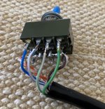
A 26G wire stripper makes the prep easy. Since there are 4 pair and only 3 pair are used, I doubled-up the wires going to pin 2 for each channel.
This looks fine - the wires are nicely twisted/bunched
Problem solved. The solution was not on the front of the PCB.
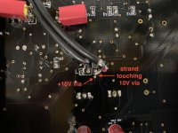
One of the jumpers on rear had a strand (removed before photo taken, and a not well centered soldering job), touching an adjacent via, which happens to be at +10V as shown in photo. I re-positioned the wire after taking the photo. All voltages now okay.
(Now I have to put all the 47Rs back in place along with a few caps.)
Attachments
Last edited:
Mine looks similar. Any SMD job where the parts stick and it works is a good job IMO. I used to fix camcorders for a living back in the '90s, but my eyes and coordination were going then. 25+ years later it ain't any better....
Problem solved. The solution was not on the front of the PCB.
One of the jumpers on rear had a strand (removed before photo taken, and a not well centered soldering job), touching an adjacent via, which happens to be at +10V as shown in photo. I re-positioned the wire after taking the photo. All voltages now okay.
(Now I have to put all the 47Rs back in place along with a few caps.)
That's great - glad you have resolved it!
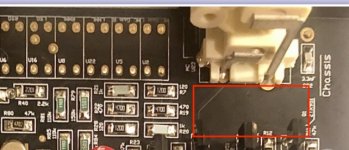
Re the two components on the MC input. These are marked RFB1 and RFB2. Please LINK THESE OUT.
They were originally fitted to offer additional RFI, but even at a few ohms series resistance they degrade the MC noise performance which is at the theoretical limit for circuit used (220-250 pV/rt Hz). Further, the dominant RFI noise mechanism is common mode and the RFB's will offer no protection against that. The solution for RFI is to wind 7-8 turns of the cable pair coming from the turntable on a large Fairite lossy toroid where the series impedance works in concert with the 3.3nF input filter caps to block RFI. I'll post a bit more up on this later (works just as well for MM inputs and applies to all MM/MC input preamplifiers BTW)
Not all boards have them. I simply jumpered RFB1,2 (so better if you do not have; one less thing to do). They're immediately adjacent to the MC input.
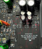
If present, RFB1,2 would be in the red box area in the attached image. (My preamp is now boxed up, so the image was taken from an earlier post of another PCB.)
If present, RFB1,2 would be in the red box area in the attached image. (My preamp is now boxed up, so the image was taken from an earlier post of another PCB.)
Attachments
Last edited:
Ah, luckily I took a picture during assembly. Does not look like I have them on my board. Hence no need to worry. Thank you for your kind reply. I am still very pleased with this . I was originally put off by the complexity. Simple is often best. But if you look most of this lies around cleaning up the power supplies. Which has no direct bearing on the signal path length. Listened feeding Class A headphone amp directly, and using Sennheiser HD600. Surprisingly nice realistic sound... I forgot to mention I used lead free solder through out. Not so easy to use, but better for the environment🙂 I had no problems though..
Attachments

- Home
- Source & Line
- Analogue Source
- Bonsai’s X-Altra MC/MM Phono Preamp