I've started listening to the preamp, only the MM section, and it is very good. It truly is quieter than record surface noise and is as quiet as my DAC. The depth of the image and the detail are excellent. So thanks Andrew for such a wonderful design and sharing with us your work!
I've sent off the 10mm thick front panel to a local engraver to have lettering put on and have the 3 holes drilled for the LEDs. It should be ready in another week or so.
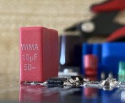
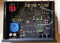
Besides using the CAT6 cable for the rumble filter, I did make another change with one capacitor set, as shown in the attached photos.
I'm not too keen on electrolytics in the signal path, so I substituted a WIMA 10uF/50V film capacitor (Mouser) for each of the four 22uF/35V bipolar caps. These have almost the same lead spacing (5 vs 3.5mm; I could not locate any in stock at Mouser with sufficient capacitance and voltage rating with a 3.5mm spacing). A slight lead adjustment with pliers to one of the pins, making the spacing closer to 3.5mm, is required prior to better fit into the PCB.
If I've calculated the f3 correctly, the spec'd 22uF/5.6k should be at ~1.2Hz. With 10uF, this increases to ~2.9Hz, which is okay with me (and not at all a factor if the rumble filter is engaged).
If 20uF is preferred, another set of the same capacitors could be soldered on the bottom of the PCB in parallel with each topside WIMA cap. Each would need to be placed on their side (they're 7.5 x 11mm square with a 16mm length).
***
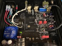
Terps: I forgot I had this photo of the whole PCB, in the upper right corner beneath the MC jack, you can see the shorted RFB1,2 pads (I only realized these needed jumpering after everything was assembled and in the box, so not the neatest job).
.
I've sent off the 10mm thick front panel to a local engraver to have lettering put on and have the 3 holes drilled for the LEDs. It should be ready in another week or so.
Besides using the CAT6 cable for the rumble filter, I did make another change with one capacitor set, as shown in the attached photos.
I'm not too keen on electrolytics in the signal path, so I substituted a WIMA 10uF/50V film capacitor (Mouser) for each of the four 22uF/35V bipolar caps. These have almost the same lead spacing (5 vs 3.5mm; I could not locate any in stock at Mouser with sufficient capacitance and voltage rating with a 3.5mm spacing). A slight lead adjustment with pliers to one of the pins, making the spacing closer to 3.5mm, is required prior to better fit into the PCB.
If I've calculated the f3 correctly, the spec'd 22uF/5.6k should be at ~1.2Hz. With 10uF, this increases to ~2.9Hz, which is okay with me (and not at all a factor if the rumble filter is engaged).
If 20uF is preferred, another set of the same capacitors could be soldered on the bottom of the PCB in parallel with each topside WIMA cap. Each would need to be placed on their side (they're 7.5 x 11mm square with a 16mm length).
***
Terps: I forgot I had this photo of the whole PCB, in the upper right corner beneath the MC jack, you can see the shorted RFB1,2 pads (I only realized these needed jumpering after everything was assembled and in the box, so not the neatest job).
.
Attachments
Last edited:
Very nice feedback and thanks for answering the question from Terps as well indeed, the layer board had place for these parts, but you just have to link them out now.
Looking forward to seeing some pictures of these completed, boxed up and with their turntable sources!
🙂
Looking forward to seeing some pictures of these completed, boxed up and with their turntable sources!
🙂
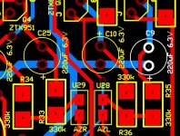
I am installing the through-hole components now. My board was from the time frame of the silkscreen change for C9 and C25. Can someone confirm the orientation in the picture in post 201 is correct for all board versions?
My is working just fine (I posted image in #201). I have no way of knowing about earlier versions, but I rather doubt a change in polarity. Those issues are usually sorted out pretty early.
I believe I did read in earlier posts about an inconsistency between the back and front of the board with respect to cap polarity, but that the front was correct. You'd have to re-read earlier posts to see if any images matched your PCB date.
I realize that there are different dates on the PCBs, but all seem to say "V1.0", which is a bit confusing.
On both C9 and C25, the cap +ve faces towards the front side of the PCB which is to the bottom in the picture below.
Attachments
Last edited:
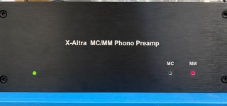
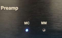
The front panel engraving, done by a local shop, was finished (LED holes were sized to 3.1mm). Attached is a photo of it on the assembled cabinet.
I did change the LEDs to different colors: green for power, blue for MC and kept the red for MM. I also added a 10K resistor in series in one leg of each LED to reduce the brightness.
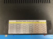
In addition, I printed out the image for the rear panel switch from the "X-Altra User Instructions" PDF file. I then taped it to the top of the cabinet: not elegant, but it works (I know I'll forget the switch functions in a few weeks).
The phono stage truly sounds very good. It is one of the best to which I've listened. (Although, I've gotten into an obsessive stage of phono preamps with different designs, and have 2 more to test; maybe I'll post a comparison at a later date. One is Pete Millett's LR phono stage. The other is one on this forum by Wyn Palmer with a very interesting 'Warp', or elliptic, filter design used instead of the typical rumble filter; the description of which can be found on this post.)
I did change the LEDs to different colors: green for power, blue for MC and kept the red for MM. I also added a 10K resistor in series in one leg of each LED to reduce the brightness.
In addition, I printed out the image for the rear panel switch from the "X-Altra User Instructions" PDF file. I then taped it to the top of the cabinet: not elegant, but it works (I know I'll forget the switch functions in a few weeks).
The phono stage truly sounds very good. It is one of the best to which I've listened. (Although, I've gotten into an obsessive stage of phono preamps with different designs, and have 2 more to test; maybe I'll post a comparison at a later date. One is Pete Millett's LR phono stage. The other is one on this forum by Wyn Palmer with a very interesting 'Warp', or elliptic, filter design used instead of the typical rumble filter; the description of which can be found on this post.)
Attachments
Last edited:
Thank you. That picture is helpful.On both C9 and C25, the cap +ve faces towards the front side of the PCB which is to the bottom in the picture below.
I searched but didn't find the answer, my board is not marked U30\U31. Are the loops the 0V points near the +15\-15 test points and are probably optional? Really close, just waiting for a better 12 pole DIP switch that is vertically oriented. $1.62, $5 shipping....
Bob, yes re the loops they are optional. There one for the 0 V as well. I use chromed paper clips and cut so the legs are about .2-.3 inches and solder those in. The holes are the correct distance apart. These make fantastic clip/test points for croc leads etc.
Quick DIY tip. If you drill holes in black anodized aluminum for LED’s, you can sometimes see the light aluminum edge around the hole. Use a black permanent marker to color the edge. Just hold the pen tip at 45 degrees and run it round the exposed corner.
This will ensure there is no silver edge to the hole and improve the finish and look. .
This will ensure there is no silver edge to the hole and improve the finish and look. .

Ah, luckily I took a picture during assembly. Does not look like I have them on my board. Hence no need to worry. Thank you for your kind reply. I am still very pleased with this . I was originally put off by the complexity. Simple is often best. But if you look most of this lies around cleaning up the power supplies. Which has no direct bearing on the signal path length. Listened feeding Class A headphone amp directly, and using Sennheiser HD600. Surprisingly nice realistic sound... I forgot to mention I used lead free solder through out. Not so easy to use, but better for the environment🙂 I had no problems though..
Just seen this - very nice soldering job Terps!
Hi, I use a stereo microscope when placing the SMT components. Which actually is a tad to high magnification when orientating to the tracks. But it is ideal to post inspect for any fine shorts between tracks. Previous life, we used bench inspection magnifiers, which are I think more suitable... Longer focal length & larger field of view. I will post some more pics of the final assembly later this week...
My SMD solder jobs are ok, but some, incl. you do a superb job. The other SMD guru is Syn08.
We are all going to have to get used to it - a lot of leaded stuff is going the way of the Dodo.
We are all going to have to get used to it - a lot of leaded stuff is going the way of the Dodo.
Finally got around to taking some pictures of the finished article in use. The only thing missing is the little button on the MC/MM switch. Thought I had one but the ones I had were to big. Still I very rarely change cartridge as it takes me around a day to line the thing up properly. Would be nice to try with a MM one day.
Attachments
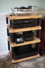
The Gyro is a nice deck. Its easy to work on unlike others. Easy to upgrade as well. I bought mine around 18 years ago with the Techno arm.
Finished up last night and hooked everything up. Unfortunately low output one channel, no output other channel 🙁 Ordered some smd probes for my multimeter. Going to take a couple days off before I jump back in. BTW the cap for the MM\MC switch is Mouser p\n 612-1R-LGR 18 cents US.... I think alcohol was involved on a couple of the build sessions which may have had some effect.
Finally got around to taking some pictures of the finished article in use. The only thing missing is the little button on the MC/MM switch. Thought I had one but the ones I had were to big. Still I very rarely change cartridge as it takes me around a day to line the thing up properly. Would be nice to try with a MM one day.
Very nice work. I like the extra safety ground to the front panel.
- Home
- Source & Line
- Analogue Source
- Bonsai’s X-Altra MC/MM Phono Preamp