Switch 9 - 12 is only the gain of the output amplifier. I was referring to the gain of the MC input preamplifier.

But otherwise I can say that the sound quality is great! I tried it over the weekend, still without the box, just for a test. Turntable DENON DP-59M + arm S + DENON DL-304 MC phone cartridge.
I still discovered the hum problem - grounding, but I solved that as well.
So I would like to say a big thank you for this famous preamp and great support in the build and recovery.
Thanks again...
I still discovered the hum problem - grounding, but I solved that as well.
So I would like to say a big thank you for this famous preamp and great support in the build and recovery.
Thanks again...
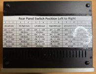
There is a gain selection option! The first 4 switches set the MC amplifier gain. If you look at the user manual which is in the supplementary data pack on the AX webpage, it will show you how to set them.
🙏 😊But otherwise I can say that the sound quality is great! I tried it over the weekend, still without the box, just for a test. Turntable DENON DP-59M + arm S + DENON DL-304 MC phone cartridge.
I still discovered the hum problem - grounding, but I solved that as well.
So I would like to say a big thank you for this famous preamp and great support in the build and recovery.
Thanks again...
The MC gain works by changing load resistor on the output of the complementary common base amplifier. So you can cater for cartridges from about 10uA output to about 100uA (in this last case, assuming you have a low coil resistance MC cart). If the switches 1-4 are all off, this leaves the load resistor at 494 ohms which is the max value. For your cart, the output is below 10uA, so we also need set the system gain stage at max gain (+9dB).
Hello Bonsai,
I am considering making your phono preamp.
I have read quite a few publications dating from 2021 concerning it and I was wondering if to date it was still possible to order the PCB from you and if so if it has been updated, in particular with the problem of inverted capas.
I have so far found almost all the matches for the components of the nomenclature updated in June 2023, but I still have one question about the reference:
On the other hand, on most mid/high-end preamps it is planned to also be able to adjust the load capacity, generally from 50 to 400pF, but I don't see this possibility on your preamp! A reason?
I am considering using an MC Hana SL cell.
Thank you in advance for the answers you would like to give me and congratulations again for your excellent work.
I am considering making your phono preamp.
I have read quite a few publications dating from 2021 concerning it and I was wondering if to date it was still possible to order the PCB from you and if so if it has been updated, in particular with the problem of inverted capas.
I have so far found almost all the matches for the components of the nomenclature updated in June 2023, but I still have one question about the reference:
- J1, J2 (Filter T/O) SIP3
On the other hand, on most mid/high-end preamps it is planned to also be able to adjust the load capacity, generally from 50 to 400pF, but I don't see this possibility on your preamp! A reason?
I am considering using an MC Hana SL cell.
Thank you in advance for the answers you would like to give me and congratulations again for your excellent work.
Hello,
Thank you for your email. I will answer you tomorrow after I get back home.
Regards
Andrew
Thank you for your email. I will answer you tomorrow after I get back home.
Regards
Andrew
Hi.
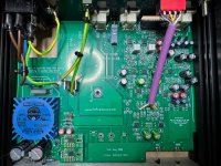
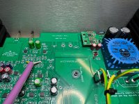
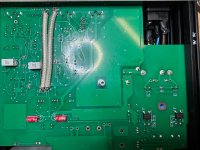
So I finished the project last week. Yesterday and today I subjected the preamp to a listening test and I can say with a clear conscience that it is the best preamp I have heard so far.
The absolute silence is shocking. MC input and the silence is absolute. My amp is humming more too. I guess it's because I manually select and match the input transistors to the MC input. And sonically, it's really a treat. It plays really well and I highly recommend anyone interested in building to start building...
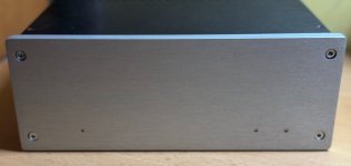
Here are some photos.
So I finished the project last week. Yesterday and today I subjected the preamp to a listening test and I can say with a clear conscience that it is the best preamp I have heard so far.
The absolute silence is shocking. MC input and the silence is absolute. My amp is humming more too. I guess it's because I manually select and match the input transistors to the MC input. And sonically, it's really a treat. It plays really well and I highly recommend anyone interested in building to start building...
Here are some photos.
Attachments
-
 20241006_152556571_iOS.jpg103.7 KB · Views: 103
 -
 20241006_152730058_iOS.jpg473.6 KB · Views: 101
 -
 20241006_150243003_iOS.jpg693.7 KB · Views: 106
 -
 20241006_150321641_iOS.jpg751 KB · Views: 114
 -
 20241006_150329289_iOS.jpg719.3 KB · Views: 108
 -
 20241006_150352417_iOS.jpg718.4 KB · Views: 109
 -
 20241006_150434296_iOS.jpg593.6 KB · Views: 101
Hello Andrew,
In order to order the components necessary to create the R.I.A.A. preamp. X-Altra MC/MM I started to check the diagram / nomenclature correspondence from the zip archive “202306081814Russel-AX-Feb2021-Update2” downloaded from hifisonix.com and from the documents:
Starting with the LEFT MC Head Amp schematic part.
On the first components except Q1 and Q2 nothing matches!? See the list below:
I have not continued further and am wondering about such differences while waiting for your response.
Kind regards.
Jean-Marc
In order to order the components necessary to create the R.I.A.A. preamp. X-Altra MC/MM I started to check the diagram / nomenclature correspondence from the zip archive “202306081814Russel-AX-Feb2021-Update2” downloaded from hifisonix.com and from the documents:
- X-Altra MCMM Schematics June 2023.pdf
- X-Altra MC_MM RIAA EQ Amp BOM June 2023.xlsx
Starting with the LEFT MC Head Amp schematic part.
On the first components except Q1 and Q2 nothing matches!? See the list below:
| Schematic | Nomenclature (BOM) |
| R35 = 330K | R35 = 220ohm |
| R36 = 330K | R36 = 470ohms |
| R11, R12 = 47K | R11, R12 = 47ohms |
| C9, C10 = 220µF/6.3V | C9 = 2.2µF/Film – C10 = 1µF ceramic |
I have not continued further and am wondering about such differences while waiting for your response.
Kind regards.
Jean-Marc
Hello,
Please download the latest BOM from the audioXpress website. The earlier one got very badly corrupted and was completely overhauled about 3 weeks ago. If you still have problems, let me know
Please download the latest BOM from the audioXpress website. The earlier one got very badly corrupted and was completely overhauled about 3 weeks ago. If you still have problems, let me know
Jean-Marc - the latest corrected BOM is at the bottom of the 1st post in this thread - September 17 2024 update 🙂
Fantastic Jardalukas! I am very happy you like the preamp and hope you will get a lot of pleasure listening to it!Hi.
So I finished the project last week. Yesterday and today I subjected the preamp to a listening test and I can say with a clear conscience that it is the best preamp I have heard so far.
The absolute silence is shocking. MC input and the silence is absolute. My amp is humming more too. I guess it's because I manually select and match the input transistors to the MC input. And sonically, it's really a treat. It plays really well and I highly recommend anyone interested in building to start building...
Here are some photos.
👍 🙂
I have updated the webpage on hifisonix.com with the correct link and made it clearer about which BOM is correct - see here https://hifisonix.com/projects/x-altra-phono-eq-preamp/
Thank you Andrew, it’s already more coherent. 🙂
I would like to make this preamp and use it with an MC cell which is recommended to be used with a load of over 400 ohms.
Is it possible to provide an adjustable resistive load and if so at what level should this modification be carried out?
On the other hand, the same for capacitives loads. On this subject, what are the capacitives loads of the MM and MC inputs of the preamp?
Regards.
Jean-Marc, this picture explains how the MC transimpedance aka current injection input stage works. You do not need the normal load resistor (usually 100-400 ohms) for this circuit topology that conventional voltage-type MC preamplifiers use. To calculate the input current to the X-Altra MC, take your cartridge output voltage and divide it by the [coil resistance + 3.25] ohms. This current flows through the amplifier output load resistor (switchable between 74 and 494 Ohms) and generates the output voltage which in most cases lies between 3 and 5 mV, but even up to 10mV is ok because the following stage (the MM RIAA amp) has 31 dB overload at 5mV - so even at 10mV you still have 24 dB overload.

Last edited:
Quick BOM Update.
For the system gain stage around U18 and U27, I had changed all the gain setting resistors to 2.2k when the PCB shows 2.7k, 2.2k and 4,7k. Please follow the PCB as this gives 4 possible gain settings and better matching to your line preamp.
Here are the part numbers for the resistors (this will be updated in the BOM in a few weeks when I do a final update)
Oh, that's bad. I have 2K2 resistors in these positions...
So I have to change these resistors according to the parts list to 2K7 and 4K7 ???
So I have to change these resistors according to the parts list to 2K7 and 4K7 ???
No, you can leave them as you have built - it just means the gain options you have are 0 dB, 6 dB and ~9 dB. If you use the resistors as I said above, you can get 0dB, 3.9dB, 7dB and 8.9dB.
🙂
🙂
Very nice looking build BTW! 👍 👍Hi.
So I finished the project last week. Yesterday and today I subjected the preamp to a listening test and I can say with a clear conscience that it is the best preamp I have heard so far.
The absolute silence is shocking. MC input and the silence is absolute. My amp is humming more too. I guess it's because I manually select and match the input transistors to the MC input. And sonically, it's really a treat. It plays really well and I highly recommend anyone interested in building to start building...
Here are some photos.
- Home
- Source & Line
- Analogue Source
- Bonsai’s X-Altra MC/MM Phono Preamp