Would it be possible to specify the values of the resistors that need to be increased? I am confused about this.
Český Krumlov is a beautiful city...
I live in Kutná Hora. Beautiful city too. But now it's been raining here for 2 days and the river levels are rising.
I live in Kutná Hora. Beautiful city too. But now it's been raining here for 2 days and the river levels are rising.
I am sorry for the confusion. I am no referring to the values of the resistors, only the count:Would it be possible to specify the values of the resistors that need to be increased? I am confused about this.
- Line 30, Item 29 of the original BOM calls for 14 resistors (the count) but there are only 13 resistors listed in the Designation column
- Line 40, Item 31 of the original BOM calls for 18 resistors (the count) but there are only 14 resistors listed in the Designation column
- Line 44, Item 35 of the original BOM calls for 6 resistors, but there are either 8 or 9 listed in the Designation column (R39 is shown twice)
- Line 67, Item 58 of the original BOM -- the Mouser part is a fused IEC receptacle but there is no fuse. A fuse needs to be added to the BOM.
Yes, I understand. Did I mean the values of the mentioned resistors? Are these 5K6 and 47K? Are these resistors for which the number of pieces needs to be increased?
Here it is again with the resistor values filled this (this is all on the BOM attached to the first posting in this thread):
- Item 29 of the original BOM (47k ohms) calls for 14 resistors (the count) but there are only 13 resistors listed in the Designation column
- Item 31 of the original BOM (220 ohms) calls for 18 resistors (the count) but there are only 14 resistors listed in the Designation column
- Item 35 of the original BOM (2.2k ohms) calls for 6 resistors, but there are either 8 or 9 listed in the Designation column (R39 is shown twice)
The latest BOM lists only 3 LM4562 but 4 are needed.
OPA 2189 there are 6 listed, only 4 needed.
22uf bipolar capacitors 6 listed, only 4 are needed.
There are many resistor quantity errors are well.
Future builders should only order with the boards on hand to double check every quantity and should not trust the BOM as of september 2024.
Parts numbers and quantities do not match the board.
I believe there must have been some sort of corruption in the file to have these many mistakes.
Yes, unfortunately it is. I will have to make another order, so more shipping. I prefer to check by motherboard.
Thanks for the heads up.
Thanks for the heads up.

Quantities are wrong in most of the items, either too many or too few.
I will be off until 06 October but when I get back I will try to send you an accurate count of each item.
I will be off until 06 October but when I get back I will try to send you an accurate count of each item.
Swapped out the transistors for that channel with BC327-40/BC337-40 to test and now the offset is at 12mV, looks like too much of a mismatch with the other ones ( 30hfe difference ).
Also Black sharpie works great for the PCB edges on the rear panel so they match the housing too.
What I did for the LED's was I only drilled a 1.5mm hole through, then drilled the LED pilot leaving about 2mm of material to the front. Just gives a nice light glow to indicate its on 👍
I used CAT6a stranded and shielded for the filter switch wiring, and then grounded the shield at the back panel end.
Build Pics attached.
Hi.
I see you used a discrete solution for the LM7815 position. Can you tell me what part it is?
Thank you.
The Kobbicon RCA receptacles I used in the original are no longer available from Mouser (obsolete)
However, an exact copy is available from Mouser made by CUI. Here is the part number (line items 48, 49 and 50 on the audioXpress hosted BOM)
https://www.mouser.co.uk/ProductDetail/CUI-Devices/RCJ-2221?qs=WyjlAZoYn50Z4/SnTBIP%2Bg==
However, an exact copy is available from Mouser made by CUI. Here is the part number (line items 48, 49 and 50 on the audioXpress hosted BOM)
https://www.mouser.co.uk/ProductDetail/CUI-Devices/RCJ-2221?qs=WyjlAZoYn50Z4/SnTBIP%2Bg==
The quantities are for the most part accurate! There may be a few line items with errors - but I will check them during this weekQuantities are wrong in most of the items, either too many or too few.
I will be off until 06 October but when I get back I will try to send you an accurate count of each item.
I started construction today and immediately encountered a discrepancy between the bill of materials and reality. I followed the description and values of the components on the motherboard.
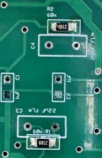
1. Part numbers do not match the description. The 68K resistor is listed as R3, R4 in the BOM... but it's actually R1, R2, R3, R4... There are a lot of mistakes and I recommend sticking to the description on the motherboard.
2. The parts list is missing parts. For example, resistors 120R, 110K, 150K...
There will probably be more, but I'm done with the job right now and I need to do a component check...
I don’t know which BOM is being used, but the BOM on the audioXpress website is prettt accurate and was checked line item by line item shortly after it was published. I’ve had very few complaints and about 60 board sets have been sold with most of those being built.
I have been very busy these last few weeks but I will make some further comments after taking a look later tonight.
I have been very busy these last few weeks but I will make some further comments after taking a look later tonight.

Why is this a huge problem? I specified 68k but called up 68.1k in the BOM because at the time Mouser had very large stocks and it was cheaper than a standard 1% 68k resistor. 68.1k vs 68k is a 0.147% shift in value and well within the 1% tolerance of the 68k device.
Rather than claim the BOM is wrong, let me know what your issues are and I can explain the reason, or, an explanatory note can be added to the BOM. I'm not claiming the BOM is perfect, but most of the issues were cleared about 2 or 3 weeks after publication when I checked it line by line for accuracy and consistency with the schematic. A BOM is always a living document because products from manufacturers change, availability goes up and down etc so it does require massaging from time to time to stay current.
In the interim, some parts have been discontinued (e.g. Kobiconn RCA PCB mount receptacle, now replaced with CUI component), and Mouser had added some that were previously only available from RS Components (e.g. binding post).
🙂
Apologies - I see your problem!
I really don't know how this has happened. Leave it with me and I will fix it in the next day or so. Again, I apologise for this and cannot explain how this happened - the part references in the BOM you have bear no relationship to the board.
I really don't know how this has happened. Leave it with me and I will fix it in the next day or so. Again, I apologise for this and cannot explain how this happened - the part references in the BOM you have bear no relationship to the board.
- Home
- Source & Line
- Analogue Source
- Bonsai’s X-Altra MC/MM Phono Preamp