I've added a note about the latest BOM in the first post of this thread. (16th December 2023 was the last update).

I wish I’d been more specific with the source waveform details!
IIRC it was a square wave. I’ll have to try to dig out my notes.
IIRC it was a square wave. I’ll have to try to dig out my notes.
I had an old modushop case from another project which will only need a new front Panel. Is
there any advantage of using all aluminum panels instead of these painted iron ones?
Front panel might be wood (with aluminum foil on the inside for screening.)

there any advantage of using all aluminum panels instead of these painted iron ones?
Front panel might be wood (with aluminum foil on the inside for screening.)
Manuel, you can use the iron cover chassis without problems. I have not tried the X-Altra MC/MM without a thick aluminium front panel. A foil screen will only provide RF screening and will not provide any protection from radiated mains noise ingress. In a correctly wired up X-Altra MC/MM preamp with a DL103 MC connected there must be zero hum from the speakers with your ear against the speaker cone and that’s what you should aim for with your build.
So, I would try it with your proposed wooden front plate and foil screen but be prepared to move to a thick front plate if you get a problem.
So, I would try it with your proposed wooden front plate and foil screen but be prepared to move to a thick front plate if you get a problem.
Hi.
Finally the board was delivered to me. Thank you very much...
I would like to ask, though. Maybe this has already been answered here. My board was made "V10 July 2020". Is this board error-free or are there any changes needed during soldering?
Thank you.
Finally the board was delivered to me. Thank you very much...
I would like to ask, though. Maybe this has already been answered here. My board was made "V10 July 2020". Is this board error-free or are there any changes needed during soldering?
Thank you.
The only thing I miss is the exact location of the components on the motherboard. There is a label on the board, but it is very, very small. I would welcome the marking of the components on the board in pdf format.
Thank you.
Thank you.
Jardakukas, your board is correct. The date on the board is there simply to identify the version - V1.0 July 2020 was the final release.
If you can read the component references on the silkscreen, you can assemble the board directly from that, but I can post up an overlay later today.
You must use a needle point soldering hit and 0.5mm diameter solder.
If you can read the component references on the silkscreen, you can assemble the board directly from that, but I can post up an overlay later today.
You must use a needle point soldering hit and 0.5mm diameter solder.
Thanks for the info.
I will be happy if you publish the layout of the components on the motherboard in pdf format.
Thank you.
I will be happy if you publish the layout of the components on the motherboard in pdf format.
Thank you.
Thanks Bonsai! Square wave 👍
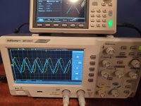
It looks good. My 100khz square wave is more triangle than what you show but I assume that isn't an issue. The others are identical.
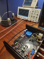
I have 2 units working.
Two things to note with final testing.
1) Both units have 50 and 80mv dc offset at MC input(at phono plugs) before DC servo is connected. When servo is connected I get +/- 0.1mv at 60 sec. Stable from there.
2) Both units, the collectors of Q1-Q4 measure 1.5v wrt 0. should be 2-3V. I checked all resistor values from pin 1 and 7 of U3 and U4 back to Q1-Q4 and they look and measure proper.. Q1-4 are not matched..
It looks good. My 100khz square wave is more triangle than what you show but I assume that isn't an issue. The others are identical.
I have 2 units working.
Two things to note with final testing.
1) Both units have 50 and 80mv dc offset at MC input(at phono plugs) before DC servo is connected. When servo is connected I get +/- 0.1mv at 60 sec. Stable from there.
2) Both units, the collectors of Q1-Q4 measure 1.5v wrt 0. should be 2-3V. I checked all resistor values from pin 1 and 7 of U3 and U4 back to Q1-Q4 and they look and measure proper.. Q1-4 are not matched..
Attachments
There are some differences between the BOM and the silkscreen on the board and schematic.
The bom had 2 - 1k resistors but there are a lot more in the board. The part number in the bom gives different values. Which should I follow?
The bom doesn’t have the 120, 150k and 110k resistors near the dip switch.
The bom had 2 - 1k resistors but there are a lot more in the board. The part number in the bom gives different values. Which should I follow?
The bom doesn’t have the 120, 150k and 110k resistors near the dip switch.
"If you can read the component references on the silkscreen"
I followed the silkscreen. Had to order a few other resistors after ordering from the bom..
I followed the silkscreen. Had to order a few other resistors after ordering from the bom..
I assume this is a typo and you mean a needle point soldering tip.You must use a needle point soldering hit and 0.5mm diameter solder.
I will be ordering a set of the PCBs (as soon as I can review the December 2023 version of the BOM). I previously had poor results soldering SMD ICs with a soldering iron. I switched to a hot air gun and soldering paste with terrific results. I have since upgraded to a WT1010N soldering station with 90W iron and an assortment of tips. I am normally most comfortable with the soldering iron -- the hot air gun was a new experience but it worked very well.
Given this information, what would you recommend that I use for the SMDs for this project? Weller soldering iron with needle point tip or my hot air gun with solder paste?
-Jon
If you are happy using the hot air gun approach then I’d stick with that. I think it gives better results than using a needle point tip - I’ve been wanting to move across to that technique for a while.
Do you know what the coil resistance of the Akiva cartridge is? From that, the output current can be calculated. In any event, I'd guess it lies between 10 Ohms and 40 Ohms in which case it is a great fit for the X-Altra MC/MM. (I wonder if it's a rebranded DL103? Maybe @billshurv knows?
Last edited:
Just check the waveform with the rumble filter switch in both positions. The test was a quick way to check the preamp functionality. I will try to get around to documenting it a bit better in the next week or so.Thanks Bonsai! Square wave 👍
It looks good. My 100khz square wave is more triangle than what you show but I assume that isn't an issue. The others are identical.
I have 2 units working.
Two things to note with final testing.
1) Both units have 50 and 80mv dc offset at MC input(at phono plugs) before DC servo is connected. When servo is connected I get +/- 0.1mv at 60 sec. Stable from there.
2) Both units, the collectors of Q1-Q4 measure 1.5v wrt 0. should be 2-3V. I checked all resistor values from pin 1 and 7 of U3 and U4 back to Q1-Q4 and they look and measure proper.. Q1-4 are not matched..
Your voltages are ok for unmatched input devices. I have come to realise the +-20~30mV offset without the servo engaged was perhaps a bit optimistic as quite a few builders have recorded higher voltages. however, the servo will do a good job of nulling these out. As noted in the write-up/supplementary data, the power consumption is very low at about 2W off the mains, so it is ok to leave it powered up permanently, which is how mine is used.
I've added the BOM to the first post. I will get the supplementary data at AX re-updated next week. To summarize:-
The production PCB is dated V1.0 July 2020
The BOM was updated in December 2023 - see sheet 1 of the BOM for the update and errata
The production PCB is dated V1.0 July 2020
The BOM was updated in December 2023 - see sheet 1 of the BOM for the update and errata
- Home
- Source & Line
- Analogue Source
- Bonsai’s X-Altra MC/MM Phono Preamp