Hi Zephyrin, here are some alternative part numbers
1. 3.2VA transformer is a Talema 70013k. You can also find it a at DigiKey their Pt# 1295-1035-ND
2. MUR820 - you can use this from Mouser 78-VS-MUR820-M3, or any of the following 771-BYW29E-200, 78-VS-MUR1520-M3, 583-SF164C
3. For the 4PDT switch I used, you can use this one from Mouser 118-1M41T1B1M1QES
Any other questions, just let me know.
3.2VA transformer is a Talema 70013k. you need to buy 125 it's not in stock at Digikey
Finaly found at Banzai. Talema PT3215. http://www.banzaimusic.com/talema-pt3215.html
For item 55 : Binding Post RS 668-4590 where can we find this part ? I have found at mouser this https://www.mouser.ch/ProductDetail/164-4200
Finaly found at Banzai. Talema PT3215. http://www.banzaimusic.com/talema-pt3215.html
For item 55 : Binding Post RS 668-4590 where can we find this part ? I have found at mouser this https://www.mouser.ch/ProductDetail/164-4200
That binding post is good.
Transformer you have found is also good.
I’ll add those sources to the next BOM update.
The Talema transformers can be difficult to get sometimes, but they are quiet. I’m surprised RS are making things difficult for you to purchase - sometimes their customer service stinks.
Transformer you have found is also good.
I’ll add those sources to the next BOM update.
The Talema transformers can be difficult to get sometimes, but they are quiet. I’m surprised RS are making things difficult for you to purchase - sometimes their customer service stinks.
Last edited:
They were impossible to order from even back in the 1980s unless they were given a Company Reg.No. each time. My experience is from the Heathrow branch for London.I’m surprised RS are making things difficult for you to purchase - sometimes their customer service stinks.

Regarding the front panel, is there any particular reason to choose 10mn instead of 4mm thickness?
I remember trying to order some stuff from them in Taiwan and I entered everything and hit the button to pay. The message came up 'You can't order from your location' - this after spending an hour rooting around on their website to find the right stuff. Eventually, I sent an email to see if I could get the stuff and got a curt 'We don't support orders blah blah'. Well, If I am trying to order from an unsupported country, why not tell me in the beginning? About 2 yrs later they changed things and you could buy some stuff from Taiwan. In Japan I used Digi-key, or some of the local distributors but then discovered Mouser who I've had fantastic service from so its who I try to use most of the time. Funny story, when I moved to mainland China from Taiwan, the Chinese authorities refused to allow me to bring my oscilloscope in. So I ordered one from Mouser and it arrived 3 days later!They were impossible to order from even back in the 1980s unless they were given a Company Reg.No. each time. My experience is from the Heathrow branch for London.
Going through checks and debugging of Phono preamp.. Here's what I have: Hope you can help and I'll keep searching!
1)The initial check power supply measurements are to specification!
With all devices mounted:
1) I now have +5.6V and +20.V at power supply???( initial test they were 8V and 23V) I assume these are the inputs to the 7815 regs as measured wrt 0V - if so the voltages are ok although a little on the low side on the V- side where you measure +5.6V.
2) I have spot on +15v/-15V - OK - that's good
3) I have+10V low noise reference +/- 100mv - Good
4) Both of 10VRC points are 9.82V??? - this is after the 47 Ohm resistors (R63 and R78) - Good.
5) I have -5VRC is -5V +/- 50mv - this is ok - good. What about the +5V supply?
6) R61 and R82 is over 5V, should be 3V problem? - this is ok - the Id vs Vsource is a bit higher on the JFE2140
7) U26 and U10 pin 7 are good - I assume you mean U26 and U19 pin 7 - should both be in range of -250 mV to +250mV
8) U27 pin 6 I get fluctuation from low MV to 170MV so there is a problem here - Check that R52 and R56 are soldered in correctly. If either of these has an unsoldered side, you will get the problems you mention. If you have used NE5534A in this location, make sure C96 is installed - if not, the opamp will be oscillating.
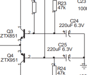
9) I have 20mv at right MC input but 80MV at Left MC input Problem Here. That is on the high side. Check that you have C9, C10 and C24 and C25 installed the right way around. If one of them is reversed (or you have a very leaky cap) you will get a large offset on the input. Also check that R11, R12 and R23 and R24 are the correct values and correctly soldered down. Can you open U28 and U29 and measure the input offset, then close U28 and U29 and remeasure it. Also, what is the voltage you are measuring at U28 and U29 after they are closed?
Note - I didn't match Q1,2,3,4 - Checking the few extra 851's vs 951's that I have, there is 200 plus HFE span. I assume this shouldn't cause the above problems but I can pull these and attempt to match.. I have 6 of each! Should be ok. Ideally you want the Vbe's of the transistors to be within 15mV of each other and then the hFE's to be closely matched. The input offset servo (U1) can servo out quite large offsets if you find you cannot get a resonalble close match. The 80mV offset is the highest I've seen which makes me tend to believe it might be an issue on the base decoupling caps or perhaps the servo circuit.
Add/Edit - I installed JFE2140DR 👍
Is this with the input short circuited or open? If the input is open, you might be picking up 60Hz noise. Can you put a scope on it?
After 18 months I'm back at it!
I've corrected the fluctuation at U27 pin 6 - It was a cracked resistor..✔
I have 80mv on the right(not left as I previously stated) MC input.. Left is <20mv
U28 and U29 are open with 80mv on right input..
U1 pin 1 measures -15V where pin 7 is +15V: the -15v on pin1, is that wrong?
Ok, what do you measure with U28 and U29 flashed closed?
Remember to measure right at the connector - so your meter -ve must go on the RCA connector. Do no measure from the PSU 0 V ad you will get errors.
Remember to measure right at the connector - so your meter -ve must go on the RCA connector. Do no measure from the PSU 0 V ad you will get errors.
U28 and 29 is closed. Right at the connector Left input at - 00.0 to - 00.1mv after 1-2 minutes and right input is taking a long time but slowly decreasing. I'm close to 10 minutes now a its at -08.7mv.. Waiting to see if 00.0 is possible
I haven't addressed the possibility of leaky C24 and C25 but they are oriented correctly.
Edit: looks like its stuck between -08.7 to -09.5mv
Edit; its out of control up to 1v swings now.. Left is fine
Edit: its unstable. probably a bad connection somewhere. I'll investigate.. Thanks!
I haven't addressed the possibility of leaky C24 and C25 but they are oriented correctly.
Edit: looks like its stuck between -08.7 to -09.5mv
Edit; its out of control up to 1v swings now.. Left is fine
Edit: its unstable. probably a bad connection somewhere. I'll investigate.. Thanks!
Last edited:
Joel,
It does seem you have a leakage and/or cap orientation problem. In the published schematic C9 and C25 are shown the wrong way around but the errata was added to the BOM and the silk screen updated a few months later. I’d suggest the following steps
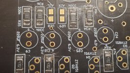
1. Double check the cap orientations - they must be the opposite of that shown in the schematic. If your PCB is marked July 2021, the cap orientation should be correct ie the silkscreen orientation is corrected
2. If that is ok, measure the voltage at pin 1 and pin 7. in an ideal case, the output voltage should not be more than +- 5~6 volts but in a really good case just a few hundred mV
3. If you are getting substantially higher voltages than this - so approaching + or - 15 volts. It means the associated opamp in U1 cannot servo out the input offset.
4. Check that the voltage at pin 3 and pin 5 is at 0V. Make sure R1, R2, R3 and R4 are reading 68k. If they are open from being cracked, it would show the problems you have.
5. If all of these things are ok, it leaves C9 and C25 as probable culprits, or U1.
Let me know how you progress
It does seem you have a leakage and/or cap orientation problem. In the published schematic C9 and C25 are shown the wrong way around but the errata was added to the BOM and the silk screen updated a few months later. I’d suggest the following steps
1. Double check the cap orientations - they must be the opposite of that shown in the schematic. If your PCB is marked July 2021, the cap orientation should be correct ie the silkscreen orientation is corrected
2. If that is ok, measure the voltage at pin 1 and pin 7. in an ideal case, the output voltage should not be more than +- 5~6 volts but in a really good case just a few hundred mV
3. If you are getting substantially higher voltages than this - so approaching + or - 15 volts. It means the associated opamp in U1 cannot servo out the input offset.
4. Check that the voltage at pin 3 and pin 5 is at 0V. Make sure R1, R2, R3 and R4 are reading 68k. If they are open from being cracked, it would show the problems you have.
5. If all of these things are ok, it leaves C9 and C25 as probable culprits, or U1.
Let me know how you progress
Thanks Bonsai
Two things off the top. I did have C9 and C25 wrong way initially but corrected them awhile ago so they are good now but leakage could still be the issue
I have changed out U1 but same conditions remain.
I'll check the rest. Thanks
actually. my board is marked V1 January 2021 and V1 May 2021 in another location
My caps are connected as drawn in my snip attachment.. Both + towards the bases of Q3 and Q4
Attachments
Last edited:
The caps were an error that slipped out in the published article on AX - they are the wrong way around. You have an early release board. Please go back and check carefully. On both those caps, the + must go to 0V. ( NB - you must not reuse electrolytic caps that have been reverse biased).
On my Boards C10 and C24 polarity markings are reversed
Attachments
Last edited:
Joel, please check the 68k resistors carefully. The input offset should settle within a few seconds - not minutes. Can you connect your meter between 0V and pin1 of U1 (right channel auto zero) and then power up and tell me what you read over the course of a few minutes, then repeat but measuring at pin 7 (left channel auto zero).
Here‘s the filter switch wiring detail
https://hifisonix.com/wp-content/uploads/2021/04/Filter-switch-wiring.pdf
Here‘s the filter switch wiring detail
https://hifisonix.com/wp-content/uploads/2021/04/Filter-switch-wiring.pdf
Last edited:
U1 pin1 and pin7 wrt 0 shows the same readings. +6v at start up and swings to -2 or 3 volts, back and forth positive/negative voltage until they settle.
After a few minutes Pin 1 settles to -0.6v and pin 7 settles to +0.1V
I checked R1,R2 and all measure 68K from U1 pins 2&6 to MC inputs- Visual check looks good
R3,R4 measure 68k from U1 pins3&5 to ground and visual check is good..
Note: Collector of Q1=-1.52 and Q4=-1.65
After a few minutes Pin 1 settles to -0.6v and pin 7 settles to +0.1V
I checked R1,R2 and all measure 68K from U1 pins 2&6 to MC inputs- Visual check looks good
R3,R4 measure 68k from U1 pins3&5 to ground and visual check is good..
Note: Collector of Q1=-1.52 and Q4=-1.65
Last edited:
- Home
- Source & Line
- Analogue Source
- Bonsai’s X-Altra MC/MM Phono Preamp