I am testing the board and measuring the different voltages.
With the U28/U29 flashed I have:
On the MC input at the connector I have 0.2mV on the left, the right input appears to be drifting between +-10/15mV
I had one of the ztx transistors soldered the wrong way, could this have damaged it? I have around 1.5V on the collectors of the 4 input transistors.
The regulator voltages are all correct, the capacitors at oriented as per the board (I also doublechecked against photos here).
MC output measured in the middle of the board is at 0.6mV both channels.
No DC offset in the output connectors.
The servo seems to correct it after a few minutes turned on, should I worry about this and order some more ztx for matching?
Could this high input offset damage the cartridge in any way during startup?
Could this high input offset damage the cartridge in any way during startup?
You have to measure the input offset across the MC input connectors. You cannot put the negative meter lead to 0V anywhere else because there will be small voltage drops across the 0V PCB tracks but they will be much greater than the servo offset.I am testing the board and measuring the different voltages.
With the U28/U29 flashed I have:
On the MC input at the connector I have 0.2mV on the left, the right input appears to be drifting between +-10/15mV
I had one of the ztx transistors soldered the wrong way, could this have damaged it? I have around 1.5V on the collectors of the 4 input transistors.
The regulator voltages are all correct, the capacitors at oriented as per the board (I also doublechecked against photos here).
MC output measured in the middle of the board is at 0.6mV both channels.
No DC offset in the output connectors.
1.5 V drop across the collectors of the ZTX input devices is ok.
There will be an offset while the servo settles, but the maximum current that can be delivered is about 2 mA for around 1-2 minutes worst case. Typically the servo will settle to within 1mV within 30 seconds and then 100uV at 2 minutes and after that quickly down to +-6 uV typical. This will not cause any damage to your cartridge.
A bipolar transistor can sustain damage if the B-E junction is reverse biased and it goes into breakdown (5-6 V). This may result in c-E leakage and/or higher noise than an unstressed part. I would try it before considering replacement. If the channel that has the stressed part is noisier, then replace it.
You don’t have to strictly match the devices, but I did on mine. I just grouped the hFE and and Vbe and used the closest pairs together.
Last edited:
I let the power on for half an hour and remeasured. My fluke 172 measures 0.1 mV in each channel MC input directly at the connectors.
I plugged it in my system and there is sound. I can’t notice any differences between channels so I would assume all is good.
I do notice some noise with maximum volume, I need to compare to my other phono stage.
The case is still missing the front panel so it might be picking up some noise. It is rather close to the speakers, could it be the 12inch woofer magnet affecting the noise?
I might order some extra stats devices with my next mouser order and match them.
Later this week I will do some listening tests but the first impression is very good!

What is the reading you get on your meter if you short the meter leads? Most meters are quite inaccurate at the very bottom of their scales.
For noise, you will get some hiss at full volume but compared to most other MC phono stages with the same overall signal chain gain, the X-Altra MC/MM will be much quieter.
Anyway, the most important thing is that when you do your listening tests, you like the sound!
For noise, you will get some hiss at full volume but compared to most other MC phono stages with the same overall signal chain gain, the X-Altra MC/MM will be much quieter.
Anyway, the most important thing is that when you do your listening tests, you like the sound!
I’ve made a YouTube video of the X-Altra MM/MC preamp here
This discusses the design and some of the constraints the two types of transducer place on the electronics.
Anyway, hope you enjoy it!
(I’ll put the link up in the first post as well)
This discusses the design and some of the constraints the two types of transducer place on the electronics.
Anyway, hope you enjoy it!
(I’ll put the link up in the first post as well)
Can hardly wait to get my arm bearings back and the new plinth for my heavily modified SP-10 fitted so that I
can test my x-Altra phono with an early Io MC by Kondo. On the assumption that all will be well that will give
me a system with all amplification by Bonsai. 😀
[I posted the gist of the above in the A6 amp thread - senile me! So at least it is now in the correct place.]

can test my x-Altra phono with an early Io MC by Kondo. On the assumption that all will be well that will give
me a system with all amplification by Bonsai. 😀
[I posted the gist of the above in the A6 amp thread - senile me! So at least it is now in the correct place.]
If I wanted to power 4-5 red leds from the power on led to create a undercase “light strip” would there any be consideration regarding current draw I would have to take in consideration? Possibly change the resistor ?
You will have to keep the load current to no more than 5-10 mA and then check that main system supply (+-15 V) is still fully in regulation using a scope.
Thanks, I might have found another way around it.
Regarding your video, very interesting and informative however it did raise a question in my non EE mind.
In the circuit diagram shown in the video you have an 100uf capacitor between the mc and mm sections. The complete schematic doesn’t seem to replicate this.
Could you explain this section of the amplifier?
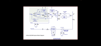
C11 and C16 couple the complementary output signal from the MC front-end stage to the gain-setting load resistor. They are high in value because the load resistor has to be able to be set to a low value (lowest is 64 Ohms) to cater for high output MC carts and you want the response to be flat down to << 20 Hz. There's about 1.5V DC across each of these capacitors, so it is not possible to directly couple the collectors of the MC front-end stage to the MM input (via the select switch U25) - the alternative here would have been some sort of diff/summing amp that would have seriously affected the noise performance.
Hope this helps!
Hope this helps!
Even if it isn't fried you can destroy the noise performance this way - never reverse-bias the E-B junction in a low noise transistor more than a couple of volts - if it undergoes zener breakdown it will stop being a low noise device due to trap sites generated by the hot carriers. Many low-noise devices and circuits incorporate a protection diode into the E-B circuit, but the ZTX951 and similar don't have this as they are made for high current switching duty.I had one of the ztx transistors soldered the wrong way, could this have damaged it?
I’ve added a video about RIAA recording and playback
I’ve added it to the first post in this thread as well.
😊
I’ve added it to the first post in this thread as well.
😊
- Home
- Source & Line
- Analogue Source
- Bonsai’s X-Altra MC/MM Phono Preamp