From what I have read about CD4, I think the high-frequency part of the signal, e.g., the modulated 30 kHz, was taken directly from the cartidge, before RIAA EQ.Even a budget cartridge with a conical needle allows you to expand the frequency response to 48 kHz if you organize the input circuit correctly and add a Neumann pole to the RIAA [] .
Cheers,
Bob
transverse to the +/-45° stereo flanks sides deep font modulation is not an adequate signal ... maybe this allows us to determine a maximum mechanical resonance of the simple spring-mass system.One could even create one on a throw-away record with a rasor blade.
From what I have read about CD4, I think the high-frequency part of the signal, e.g., the modulated 30 kHz, was taken directly from the cartidge, before RIAA EQ.
Cheers,
Bob
This is what Dagfinn tolds me:
CD4 demodulation happened prior to RIAA network. In addition it was used a 100kR load, giving additional HF lift. According to http://www.pspatialaudio.com/JVC_CD-4.htm, "Needle-drops must be be recorded without RIAA equalisation1. Attenuation of the upper sidebands of the CD-4 FM signals due to RIAA filtering is over 46dB relative to the baseband. Thus ninety-nine percent of the FM carrier level is lost in the RIAA filter and the FM tracks are reduced to 8-bit resolution. Our experiments have shown that reliable CD-4 FM carrier recovery is not possible with RIAA equalised needle-drops."
CD-4From what I have read about CD4, I think the high-frequency part of the signal, e.g., the modulated 30 kHz, was taken directly from the cartidge, before RIAA EQ.
complete discrete four channel
First of all, set the maximum speed at f1k to 2.23 cm/sec and ensure that the difference channels are recorded at a constant speed. While the unmodulated carrier f30k (with its speed of 3.54 cm/sec) has a level of -19dB below the normal main channel. The smallest wavelength is now around 5.4µm and f30k+15kHz, which is why the Shibata needle is required. Both FM and PM are used as modulation, differentiated for frequencies <0.8kHz and >0.8kHz. The sum signal, the main channel, is band-limited (fh=15kHz), but the lower sideband and the main channel still overlap significantly.
Our gut feeling tells us that the overall resulting SNR can't be particularly good - and that's the case, we have to use our own noise suppression.
The details can be found in the technical literature of the late 1970.
It is not necessary for the MM pickup to have a perfectly linear sensitivity / transfer up to 50kHz, but a special stylus cut is.
HBt.
Since the recording, i.e. the cutting process, is carried out with RIAA preemphasing up to 45kHz, it is very likely that RIAA EQ (up to and including 45kHz) will be used for amplification before the first matrix, demodulation and the next matrix ... plus delays, NR, automatic level adjustments ...
this process is not quite so trivial.
this process is not quite so trivial.
There are a few thing to consider in general but even more when looking at CD4.
1) There is Fres from the tip in the vinyl groove that’s dependent on the ETM according to the fr = (0.632/πSqrt(m)*(E0²FvR)^1/6
ETM (equivalent tip mass m) is the dominant factor for the achievable BW proportional to 1/sqrt(m).
The tip diameter R plays a much lesser role.
See documentation from Technics to show the effect of ETM to Bandwidth and Fr.

Of course the cantilever's suspension can be used to flatten the FR as can be seen in the calculated transfer functions below.

2) And there is the Fcutoff that is dependent on the tip diameter according to fc = 1.51(V/π)*(E0/FvR)1/3
Here the tip diameter R as well as the stylus force Fv are inverse proportional to the power 1/3.
However, a higher Fv may damage the CD4 track.
Looking at the image below it’s obvious that a 0.65mil round tip with low ETM and stylus force of 1.5g could only play a CD4 LP up to 20cm diameter.
However, a 3um tip radius would lift the whole graph by a factor 2 and plays a CD4 LP up to the inner circle.

3) And finally there is the Cart’s termination resistance and capacitance that has to be used to get a proper balance in FR between mechanical and electrical part.
And in some cases the BW can be extended by changing the termination load, but there is no way to avoid the cutoff frequency with a tip with a too large diameter.
And when having extended the BW for a cart with a higher ETM, the S/N will be affected the more lift is given to the mechanical roll off.
So to play a CD4 LP you will need both a very low ETM and a very small tip diameter.
That's why the Shibata tip was mandatory to play CD4
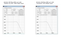
This is another table from Dagfinn with Audio Technica carts where only the last was specially made for CD4.

Quite remarkable is that they all were advised to use a 47K termination and for the shibata version from 47K to 100K , preferably with a short interlink to keep capacity low.
For the Shibata Cart with the high BW, a 370mH coil was used to shift the generator's Fr into a higher frequency, like Technics also did for their high BW carts.
Hans
1) There is Fres from the tip in the vinyl groove that’s dependent on the ETM according to the fr = (0.632/πSqrt(m)*(E0²FvR)^1/6
ETM (equivalent tip mass m) is the dominant factor for the achievable BW proportional to 1/sqrt(m).
The tip diameter R plays a much lesser role.
See documentation from Technics to show the effect of ETM to Bandwidth and Fr.
Of course the cantilever's suspension can be used to flatten the FR as can be seen in the calculated transfer functions below.
2) And there is the Fcutoff that is dependent on the tip diameter according to fc = 1.51(V/π)*(E0/FvR)1/3
Here the tip diameter R as well as the stylus force Fv are inverse proportional to the power 1/3.
However, a higher Fv may damage the CD4 track.
Looking at the image below it’s obvious that a 0.65mil round tip with low ETM and stylus force of 1.5g could only play a CD4 LP up to 20cm diameter.
However, a 3um tip radius would lift the whole graph by a factor 2 and plays a CD4 LP up to the inner circle.
3) And finally there is the Cart’s termination resistance and capacitance that has to be used to get a proper balance in FR between mechanical and electrical part.
And in some cases the BW can be extended by changing the termination load, but there is no way to avoid the cutoff frequency with a tip with a too large diameter.
And when having extended the BW for a cart with a higher ETM, the S/N will be affected the more lift is given to the mechanical roll off.
So to play a CD4 LP you will need both a very low ETM and a very small tip diameter.
That's why the Shibata tip was mandatory to play CD4
This is another table from Dagfinn with Audio Technica carts where only the last was specially made for CD4.
Quite remarkable is that they all were advised to use a 47K termination and for the shibata version from 47K to 100K , preferably with a short interlink to keep capacity low.
For the Shibata Cart with the high BW, a 370mH coil was used to shift the generator's Fr into a higher frequency, like Technics also did for their high BW carts.
Hans
Last edited:

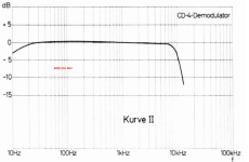
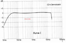
Grundig CD4 Demodulator / Decoder
Based on this circuit, we can find out in detail how the quadraphonic process of the 1970s must have worked.
No more speculation! I doubt whether this excursion will catapult us any further forward in terms of normal stereo playback of a long-playing record.
All points concerning the pickup and its mechanics are completely undisputed.
HBt.
Attachments
Returning to Mr. Polak's system identification, I submit that we need an inverted sine sweep (log) from 100kHz to 1kHz (two decades) and this can only be on a 45rpm test record cut at half or quarter speed, if that is possible at all. I don't know whether this is possible with the DMM method.
Constant velocity (means without RIAA Preemphase).
🤔
Constant velocity (means without RIAA Preemphase).
🤔
Bob,
It´s absolutely great that we can have this discussion without drama, on the other hand can you imagine how hard it is for me to argue with facts against the opinion that damping will give an overall improvement in frequency response, where the extended FR for a damped Generator is undisputed
From my side all presented material is based on facts derived from measuring with the greatest possible care and from mathematical support from people like Bastiaans, where you still seem to have the feeling that results are questionable to some degree where it concerns damping with a pole around 8KHz to achieve an improved bandwidth and/or frequency response.
However even with all data gathered correctly and with the greatest possible care, it´s always possible that in the interpretation of these data things are overlooked, critique for which I´m fully open.
A few possible points concerning the interpretation were mentioned by you such as eddy currents and validity of the used test disk with pink noise up to almost 30Khz.
The eddy current seems to be no longer an issue and may I assume that the 30Khz pink noise test disk is as good as it can be for collecting transfer responses.
It may very wel be that we have different opinions on how useful it is to extend the frequency range into the ultrasound range.
I have conducted test with hi res 24/192Khz CD’s with lots of ultrasound like from cembalos, where downgrading was done with uncorrelated rubbish to resp. 16/192Khz and to 16/44.1Khz, but still in the 24/192Khz envelope. The ones that were most convinced to be able to hear beyond 20Khz, selected the 16/44.1 version as being the original !
Many other tests by reputable institutes came to comparable conclusions, but some disputed papers claiming the opposite keep popping up all the time.
So let’s say this subject is inconclusive and I have my personal opinion.
Question number one to be asked is what purpose did you have in mind when opting for an extended bandwidth for a Cart that’s perfectly able to reproduce up to 20Khz, was it to extend FR into the ultrasound range or was it to achieve an improved impulse response.
In our discussion that’s quite vital.
I respect your opinion when you think that ultrasound adds to the quality of the perceived sound, but when your goal is to get an improved impulse response, that’s where I can try to show with models if any and what sort of effects can be achieved.
Question number two is whether you have any life recorded material with and without damping to support your idea that damping may improve things, that would really be helpful in our discussion.
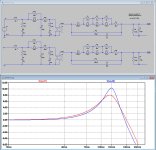
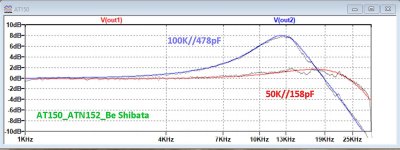
As a final attempt to prove things I’ve made simulations for two cart models, both having the same FR with the 50K//158pF termination as recorded with the AT150-ATN152.
To achieve this, it’s obvious that when the mechanical has been changed, the generator will have to be changed also to achieve the same FR with 50K//158pF between the two models.
But in both versions the basic 360mH and 665R Cart properties are still kept intact.
However, when applying the second 100K//478pF recorded termination for the AT150-ATN152, you can see that only one of the two models conforms to the life recorded FR with that second termination load.
See below the original image as published in my paper with recorded signal versus simulated signal, both being almost within +/- 0.1dB when flattened.
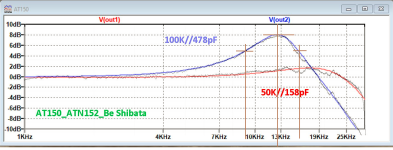
Second attachment shows the two different models, but having the same FR when terminated with 50K//158pF.
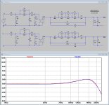
In the third attachment, when both being loaded with 100k//478pF, there is a large difference of 2dB around 13Khz.
This should do as a prove that only one set of models for the mechanical part and the Generator can exist, ergo the replacement model for the mechanical part has to be correct.
But also the model for the generator has to be correct for the same reason and using the reciprocity when turning the Generator from Impedance into a model worked out to be correct.
When the models for as well the mechanical part and also for the Generator are correct, then a simulation showing the effect of damping can only be correct also.
And although the extended FR for the Generator is undisputed when applying damping, fact remains that while increasing the Generator's BW at the same time it will have impact on the overall FR that depends on the mechanical response as shown in #184 and in #206.
So a life recording from you with and without damping should be welcome.
Hans
It´s absolutely great that we can have this discussion without drama, on the other hand can you imagine how hard it is for me to argue with facts against the opinion that damping will give an overall improvement in frequency response, where the extended FR for a damped Generator is undisputed
From my side all presented material is based on facts derived from measuring with the greatest possible care and from mathematical support from people like Bastiaans, where you still seem to have the feeling that results are questionable to some degree where it concerns damping with a pole around 8KHz to achieve an improved bandwidth and/or frequency response.
However even with all data gathered correctly and with the greatest possible care, it´s always possible that in the interpretation of these data things are overlooked, critique for which I´m fully open.
A few possible points concerning the interpretation were mentioned by you such as eddy currents and validity of the used test disk with pink noise up to almost 30Khz.
The eddy current seems to be no longer an issue and may I assume that the 30Khz pink noise test disk is as good as it can be for collecting transfer responses.
It may very wel be that we have different opinions on how useful it is to extend the frequency range into the ultrasound range.
I have conducted test with hi res 24/192Khz CD’s with lots of ultrasound like from cembalos, where downgrading was done with uncorrelated rubbish to resp. 16/192Khz and to 16/44.1Khz, but still in the 24/192Khz envelope. The ones that were most convinced to be able to hear beyond 20Khz, selected the 16/44.1 version as being the original !
Many other tests by reputable institutes came to comparable conclusions, but some disputed papers claiming the opposite keep popping up all the time.
So let’s say this subject is inconclusive and I have my personal opinion.
Question number one to be asked is what purpose did you have in mind when opting for an extended bandwidth for a Cart that’s perfectly able to reproduce up to 20Khz, was it to extend FR into the ultrasound range or was it to achieve an improved impulse response.
In our discussion that’s quite vital.
I respect your opinion when you think that ultrasound adds to the quality of the perceived sound, but when your goal is to get an improved impulse response, that’s where I can try to show with models if any and what sort of effects can be achieved.
Question number two is whether you have any life recorded material with and without damping to support your idea that damping may improve things, that would really be helpful in our discussion.
As a final attempt to prove things I’ve made simulations for two cart models, both having the same FR with the 50K//158pF termination as recorded with the AT150-ATN152.
To achieve this, it’s obvious that when the mechanical has been changed, the generator will have to be changed also to achieve the same FR with 50K//158pF between the two models.
But in both versions the basic 360mH and 665R Cart properties are still kept intact.
However, when applying the second 100K//478pF recorded termination for the AT150-ATN152, you can see that only one of the two models conforms to the life recorded FR with that second termination load.
See below the original image as published in my paper with recorded signal versus simulated signal, both being almost within +/- 0.1dB when flattened.
Second attachment shows the two different models, but having the same FR when terminated with 50K//158pF.
In the third attachment, when both being loaded with 100k//478pF, there is a large difference of 2dB around 13Khz.
This should do as a prove that only one set of models for the mechanical part and the Generator can exist, ergo the replacement model for the mechanical part has to be correct.
But also the model for the generator has to be correct for the same reason and using the reciprocity when turning the Generator from Impedance into a model worked out to be correct.
When the models for as well the mechanical part and also for the Generator are correct, then a simulation showing the effect of damping can only be correct also.
And although the extended FR for the Generator is undisputed when applying damping, fact remains that while increasing the Generator's BW at the same time it will have impact on the overall FR that depends on the mechanical response as shown in #184 and in #206.
So a life recording from you with and without damping should be welcome.
Hans
Attachments
With an increase of resistance, it is logical to decrease the capacity, but here you have the opposite. How is that possible ?when applying the second 100K//478pF recorded termination
Attachments
W wouldn't believe what we can quickly extract from a graphic ?!
Please take this as a good estimate. No more and no less. This approach is not 100% correct. Let's see it as an approximation. And so it goes with the disenchantment:
f1 = 9.083kHz
fc = 12.49kHz
f2 = 15.6kHz
fo = sqrt(f1 * f2)
= 11.904kHz
L = (1/ 478pF) * 1 / (2*PI*fo)^2
= 374mH
Z´= sqrt( L/C)
= 27.97kOhm
b = f2 - f1
= 6.517kHz
Q = fo / b
= 1.83
Z = Rl / Q
= 100kOhm / 1.83 = 54.644kOhm
===>
sqrt( (54.644kOhm)^2 - (27.97kOhm)^2 ) = 46.943kOhm this is the correct termination of this pickup, it follows in the further rollover:
fh = 19.976kHz
Rp < 47kOhm
Cp = 169.7pF
Q = 1 !!!
The red curve fully confirms the rollover. Now I ask myself what Mr. Polak's mission is actually about?
Attachments
That's a good point Hans P. :
Something essential is missing in a correct (really complete) model of our transducer.
+1
HBt.
If the mechanical, i.e. the moving part is changed -> for example the mass, the damper, the suspension and the armature in the yoke, i.e. our moving permanent magnets (magnetic flux) -> then the generator model also changes ..!To achieve this, it’s obvious that when the mechanical has been changed, the generator will have to be changed also to achieve the same FR with 50K//158pF between the two models.
But in both versions the basic 360mH and 665R Cart properties are still kept intact.
Something essential is missing in a correct (really complete) model of our transducer.
+1
HBt.
When investigating Cart’s we went by purpose far outside the usual comfort zone to get the assumption proved that the Cantilever’s assembly reponse is not influenced by whatever termination is used.With an increase of resistance, it is logical to decrease the capacity, but here you have the opposite. How is that possible ?
It was not at all to extend the frequency range with a higher resistance value and a lower capacity like you did.
Hans
Yes, sure. But most advanced modern both MM and MC cantilevers are sapphire tube/beryllium/boron pipe with <0,25 mg effective-tip-mass and >30 kHz mechanical resonance. And in any case (up to 150k), greater resistance does not lead to a roll-off of higher frequencies.It was not at all to extend the frequency range with a higher resistance value and a lower capacity like you did.
Last edited:
Using a higher capacity and a lower resistance as in the case you refer to, leads to a higher Q on a lower frequency thus to a more pronounced and more dominant peak in the overall response because of the Generator, exactly what can be seen in the shown image.Yes, sure. But most advanced modern both MM and MC cantilevers are sapphire tube/beryllium/boron pipe with <0,25 mg effective-tip-mass and >30 kHz mechanical resonance. And in any case (up to 150k), greater resistance does not lead to a roll-off of higher frequencies.
Again, it was not the intention to change the FR in any direction, it was just using random termination numbers on totally different carts, all with the same outcome that the cantilever assembly was not affected in any way by the termination load on the Generator, which was exactly the thing to be prove.
Hans
When investigating Cart’s we went by purpose far outside the usual comfort zone to get the assumption proved that the Cantilever’s assembly reponse is not influenced by whatever termination is used.
Let me translate that for us:
We only wanted to find an equivalent electrical model that can show the influence on the combined transmission behavior - linearly! We ignore the physical, mechanical part. We simply fill the longitudinal and transverse links of our electrical network until the frequency response determined by measurement (with the values varied by the variances) matches the electrically simulated (or calculated) frequency response as closely as possible.
We recorded digitally at 24Bit and 96kHz (maybe also at 24Bit and 192kHz), the excitation signal was either a band-limited pink noise signal or a logarithmic sine sweep (it's hard to know exactly, because I express myself differently at different points). The upper cut-off frequency of the test signal on the CH-Precision test record is possibly 30 or even a little more kilo Hertz.
Our knowledge of parallel and serial basic elements, the classical oscillating circuits, came to our aid.
#
Dear Mr. Polak,
do you know what else I would wish - more details ... and, above all, connections and returns.
Kind regards,
hbt.audio
Attachments

Q is proportional to RloadUsing a higher capacity and a lower resistance as in the case you refer to, leads to a higher Q on a lower frequency thus to a more pronounced and more dominant peak in the overall response because of the Generator, exactly what can be seen in the shown image.
f is inversely proportional to the product 2*PI*sqrt( L * C )
Dear Hans Polak,
your quick statements are often full of errors.
I'm sorry.
Excuse me, but any mechanical engineering student or /of physics, electronics ... would have come to this groundbreaking realization - in the first semesters could have given it to you immediately - with a conclusive explanation.Again, it was not the intention to change the FR in any direction, it was just using random termination numbers on totally different carts, all with the same outcome that the cantilever assembly was not affected in any way by the termination load on the Generator, which was exactly the thing to be prove.
Hans
Bye,
HBt.
PS
Perhaps this is all a point that makes Bob C. desperate or a little irritated. I personally feel that way.
That's the crucial point,it was just using random termination numbers on totally different carts,
purely by chance and somehow,
that's why I asked in the other thread about your methodical approach and about the measurement chain ..!
But we can put this point to bed. Since you don't want to provide any detailed and consistent information on this, it reduces the value of your work enormously. In everyday university life, it would even be worthless in the form you have given it.
And it is precisely this point (also that of denial) that leaves me sad. Because the work could be so valuable, could.
Now I would like to quietly withdraw and just think about Bob's thread and intention.
kindly,
HBt.
- Home
- Source & Line
- Analogue Source
- Bob Cordell's VinylTrak