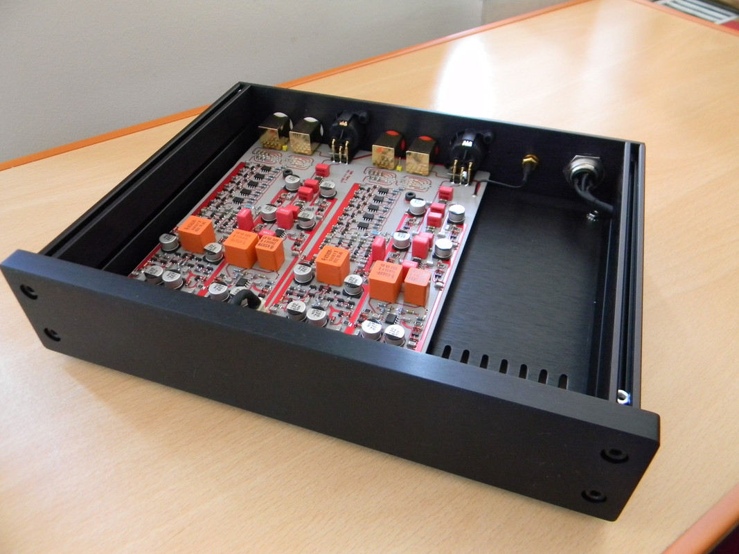
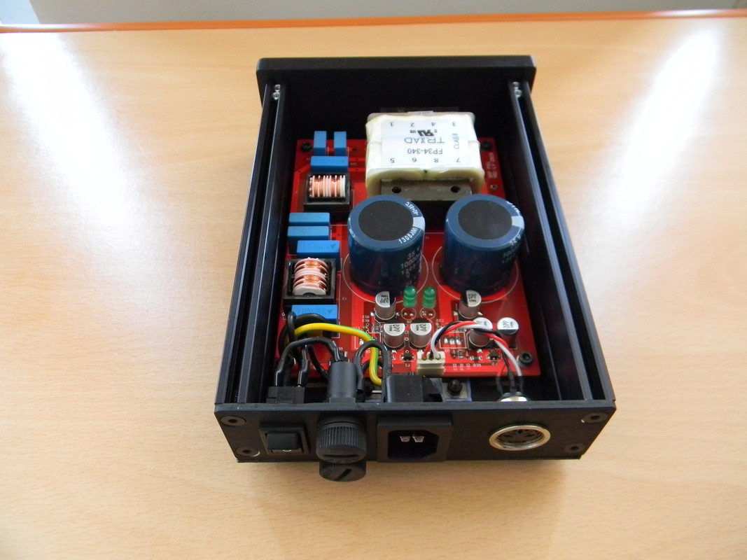
Some measurements
(SRP-MC my version of Bob Cordell`s VinylTrak)
To be cont.
Looks good!
Cheers,
Bob
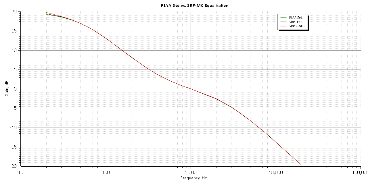
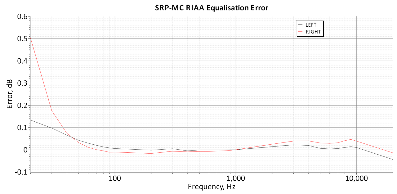
It is interesting that in the right channel there is a delta 0.35 dB with the left channel.
Probably because some mismatch in DC-Servo components values.
Probably because some mismatch in DC-Servo components values.
It is interesting that in the right channel there is a delta 0.35 dB with the left channel.
Probably because some mismatch in DC-Servo components values.
Yes, I noticed that. The delta begins to exceed 0.1 dB at 30 Hz. You are probably right about it being the DC servo.
Cheers,
Bob
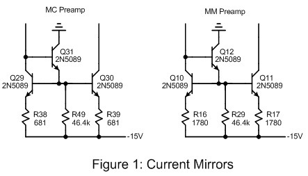
I have a question regarding Wilson current mirror. Do I have to match Q10 and Q11 (Q29 and Q30 as well) for better performance?
Matching not needed 🙂
Hey Dontsov,
Since none of the experienced builder here has answered you yet, I'll give it a try. It is better than nothing, right? 🙂
In general, matching in audio will *always* give you a better performance. However, there is a point of diminishing returns. If I would build the VinylTrak, I would not match Q10/11 resp. Q29/Q30. My reasoning is as follows:
I assume you would match beta of the BJTs. I am very sure that the performance of the VinylTrak is mainly limited by the matching of (the Idss of) the input JFETs. That is why Bob uses dual JFETS (sry, can't find the thread righ now). Compared to the variation between the individual FETs, the input/output current variation in the current mirror due to unmatched beta of the BJTs will typically be negligable, especially since beta is already very high for the 2N5089. Therefore, I would rather spend my time listening to the preamp than matching transistors. 🙂
BUT, if you already have matched the transistors, of course use them. There is nothing to loose here. 😉
By the way, Bob found later that a 3-transistor current mirror gave better noise performance, see http://www.cordellaudio.com/preamplifiers/vinyltrak.shtml. I added the picture below.
I hope it helps 🙂
JB
JB,
Thanks for your comments! I've finally decided to play it safe and put in a matched dual transistor in the current mirror. But what you are saying absolutely makes sence.
P. S. Haven't got an answer notification, although I'm pretty sure I subscribed to this thread....
Thanks for your comments! I've finally decided to play it safe and put in a matched dual transistor in the current mirror. But what you are saying absolutely makes sence.
P. S. Haven't got an answer notification, although I'm pretty sure I subscribed to this thread....
@ Bob Cordell
Hi Bob
I am studying the schematic of the VinylTrak published in linear Audio Vol4 page 139...
Everything is quite clear to me but one transistor:
Q9 is a common base inside the loop of the wilson mirror..... would you care to explain it's function ?
Best regards
Ricardo
Hi Bob
I am studying the schematic of the VinylTrak published in linear Audio Vol4 page 139...
Everything is quite clear to me but one transistor:
Q9 is a common base inside the loop of the wilson mirror..... would you care to explain it's function ?
Best regards
Ricardo
One more question,in the document of Volume 4 of Linear Audio Figure 6, I can see the D1 and D2 in the Figure,but it show empty there?does it a switch to control the C5 and C6?
Thanks
Leo
Thanks
Leo
With all respect, you should read the article. Or do a 'find' on D1 for instance.
The absence of NFB allows the 75us RIAA time constant to be implemented with a hand-selected combination of 2 polystyrene shunt capacitors totaling 0.02uF at the high-Z VAS node. This means that the amplifier need not ever swing the amount of voltage that would otherwise occur at high frequencies if the amplifier had a flat gain of 10. Nodes D1 and D2 are connected to ground through relay contacts for conventional equalization. The contacts are opened for damped EQ, inserting a zero at 8kHz via R19.
Jan
Yes,yes,find it.thanks Jan againWith all respect, you should read the article. Or do a 'find' on D1 for instance.
The absence of NFB allows the 75us RIAA time constant to be implemented with a hand-selected combination of 2 polystyrene shunt capacitors totaling 0.02uF at the high-Z VAS node. This means that the amplifier need not ever swing the amount of voltage that would otherwise occur at high frequencies if the amplifier had a flat gain of 10. Nodes D1 and D2 are connected to ground through relay contacts for conventional equalization. The contacts are opened for damped EQ, inserting a zero at 8kHz via R19.
Jan
Can I use the 2sk489 to replace for BOTH the 2sk389 and LS844?
But check the datasheet the 2sk489 noice is 1.8nv and 2sk389 only 1.3nv,still better than 2SK489.
Which grade 2SK389 should be used.A,B or C?
But check the datasheet the 2sk489 noice is 1.8nv and 2sk389 only 1.3nv,still better than 2SK489.
Which grade 2SK389 should be used.A,B or C?
I have checked Linear system for the 2SK389,seems like EOL,no stock and can not put the order.
is there any other parts to replace for 2SK389? I have almost 200pcs 2sk170GR ,can I use this one to replace 2sk389?
is there any other parts to replace for 2SK389? I have almost 200pcs 2sk170GR ,can I use this one to replace 2sk389?
Dear Jan,thanks. Do you know which grade will be used ?2SK389A,or 2SK389B,I guess It should be B grade.
Can I use the 2sk489 to replace for BOTH the 2sk389 and LS844?
But check the datasheet the 2sk489 noice is 1.8nv and 2sk389 only 1.3nv,still better than 2SK489.
Which grade 2SK389 should be used.A,B or C?
The LSK389 has significantly lower voltage noise than the LSK489. They are both very good parts, but optimized for different applications. The LSK389 is a large die with high transconductance that leads to very low noise. However, as a result, its capacitances are larger. The LSK489 is a smaller die with quite low capacitances and smaller transconductance, and yet still achieves low noise performance, just not as low as that of the LSK389. Use of the LSK389 is particularly important in the MC part of the preamp. The LSK489 can and should generally be used instead of the older LS844.
These parts are readily available from Linear Systems. Look for the LSK parts rather than the 2SK parts. The old Toshiba 2SK389 is no longer available. I usually recommend using the B version of the LSK389.
Cheers,
Bob
Bob,thanks for you detail input.that is clear
- Home
- Source & Line
- Analogue Source
- Bob Cordell's VinylTrak