Jan: “It is nonsense to test an audio amplifier with an infinite bandwidth signal and then think you can give a meaningful comment on how they will perform as an audio amplifier.”
Engineers are testing audio amplifiers with a square wave signal with an even wider spectrum and a slew rate of theoretically infinity and do not consider this nonsense. Although a long time ago Baxandall found that the maximum slew rate of real sound signals does not exceed 0.5 V / μs. Nevertheless, having measured the SR of two amplifiers and received 15 V / μs for one and 150 V / μs for the second, we are sure that the second one will sound better. I just gave examples of how to measure practically velocity distortion at the development stage. If you are not interested in this parameter, then don't do it.
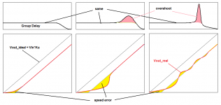
There is no ideal in real output signal (black line). The task of the developer is to make such an amplifier so that the real output voltage is as close as possible to the ideal
Engineers are testing audio amplifiers with a square wave signal with an even wider spectrum and a slew rate of theoretically infinity and do not consider this nonsense. Although a long time ago Baxandall found that the maximum slew rate of real sound signals does not exceed 0.5 V / μs. Nevertheless, having measured the SR of two amplifiers and received 15 V / μs for one and 150 V / μs for the second, we are sure that the second one will sound better. I just gave examples of how to measure practically velocity distortion at the development stage. If you are not interested in this parameter, then don't do it.
There is no ideal in real output signal (black line). The task of the developer is to make such an amplifier so that the real output voltage is as close as possible to the ideal
Last edited:
Bonsai: “In my post above I meant to say artefacts >> higher in frequency than the stimulus signal (assumed to be a 20 kHz sine wherein the amplitude is changed instantaneously) ”
In fact, there is no instantaneous change in the amplitude of the signal, the signal changes at the moments of crossing zero and without breaking the phase!
There is an anecdote about measuring the parameters of amplifiers: A seriously ill patient is brought to the doctor, the doctor measures the temperature - the temperature is normal, 36.6; measures pressure - pressure 120/80. The doctor says to the patient: You are fooling, you are healthy! And the patient dies ... because the doctor did not measure to make a correct diagnosis.
So the developers of audio amplifiers (including myself) have measured the coefficient of nonlinear distortion all their lives, which does not correlate in any way with the sound quality and, at best, the level of intermodulation distortion, which also weakly correlates with the sound quality.
So the developers of audio amplifiers (including myself) have measured the coefficient of nonlinear distortion all their lives, which does not correlate in any way with the sound quality and, at best, the level of intermodulation distortion, which also weakly correlates with the sound quality.
Do you consider this speed distortion to be the major determining factor of amplifier's perceived quality? Can you explain psychoacoustics of it? Any reference (beside C. Hammer) to a research backing it?
There is an instantaneous change in the slope of the wave when it goes thorough zero crossing, however. New frequencies are thus created (so to speak).
Overall though, I think petr_2009 is on to something. What early stage unpublished research may find can still be true. Also, much research is now proprietary. I am speaking of testing amplifiers in a way that is found to correlate with perceived sound quality. If it works, it works, the problem then is to figure out how and why. IMHO, one can't keep up with progress if one only accepts peer reviewed journal articles as evidence.
Overall though, I think petr_2009 is on to something. What early stage unpublished research may find can still be true. Also, much research is now proprietary. I am speaking of testing amplifiers in a way that is found to correlate with perceived sound quality. If it works, it works, the problem then is to figure out how and why. IMHO, one can't keep up with progress if one only accepts peer reviewed journal articles as evidence.
Last edited:
Some points which concern me:
- in an amplifier system the preamp, signal source and power amp all have some bandwidth limit. If a power amp has a low bandwidth, say 20kHz, and the rest of the system also 20kH that will combine to create a poor 10kHz roll-off. Then a 200kHz power amp is needed to get close to the overall 20kHz bandwidth. Are we considering the power amp to correct for other limitations? Not unncessarily, perhaps, but might explain some differences.
- any change of amplitude of a sineburst (a sinewave is continuous, so any sinewave-like but time-limited signal is a burst and has high frequency harmonics). I don't see the difference between a change of amplitude in a sinewave burst than a full stop as in a tone burst test. Both create a discontinuity which the amplifier has to deal with. In that respect a tone burst is a limiting case of the amplitude change, so I don't see the need for a continuing wave at a different amplitude unless the introduction of a time delayed response - common to all signals in a given amplifier - while simultaneously handling the after effects of the tone burst creates a situation not simulated by a tone burst alone. Is that the case?
Furthermore, a loudspeaker which has been responding to the sineburst will have a momentum as it reaches its zero crossing. That will tend to continue and will only be controlled by the amplifier's damping capability. That adds to potential signals the amplifier has to deal with.
I suspect that these effects and how the amplifier handles them could be significant, not necessarily by bandwidth alone.
Last edited:
Journal articles should be accepted as journal articles. Test results should be accepted as evidence.IMHO, one can't keep up with progress if one only accepts peer reviewed journal articles as evidence.
Bonsai: “In my post above I meant to say artefacts >> higher in frequency than the stimulus signal (assumed to be a 20 kHz sine wherein the amplitude is changed instantaneously) ”
In fact, there is no instantaneous change in the amplitude of the signal, the signal changes at the moments of crossing zero and without breaking the phase!
There is an anecdote about measuring the parameters of amplifiers: A seriously ill patient is brought to the doctor, the doctor measures the temperature - the temperature is normal, 36.6; measures pressure - pressure 120/80. The doctor says to the patient: You are fooling, you are healthy! And the patient dies ... because the doctor did not measure to make a correct diagnosis.
So the developers of audio amplifiers (including myself) have measured the coefficient of nonlinear distortion all their lives, which does not correlate in any way with the sound quality and, at best, the level of intermodulation distortion, which also weakly correlates with the sound quality.
It does not matter where you change the amplitude, you will still get HF artefacts - this quite normal amplifier behaviour, and not distortion.
The rate of change at the zero crossing must be higher for the same frequency with a higher voltage and what you are seeing is the amplifier loop responding to that by supplying more current into the second (integrator) stage. If you change from a higher voltage to a lower voltage, the input stage has to suck additional charge out of the integrator, so it applies in both directions i.e. going bigger and going smaller in signal level. The vector error you showed in your earlier plot is standard integrator behaviour and standard VFA behaviour also - its quite normal.
Obviously if you push it too hard, the amplifier will slew, but we know very well how to prevent this with good design practice.
Anyway, I wont have an argument about this. Life it too short.
🙂
Last edited:
There is an instantaneous change in the slope of the wave when it goes thorough zero crossing, however. New frequencies are thus created (so to speak).
Overall though, I think petr_2009 is on to something. What early stage unpublished research may find can still be true. Also, much research is now proprietary. I am speaking of testing amplifiers in a way that is found to correlate with perceived sound quality. If it works, it works, the problem then is to figure out how and why. IMHO, one can't keep up with progress if one only accepts peer reviewed journal articles as evidence.
Come on. This stuff is very well known.
chip_mk: “Do you consider this speed distortion to be the major determining factor of amplifier's perceived quality? Can you explain psychoacoustics of it? Any reference (beside C. Hammer) to a research backing it?”
There are publications of studies by Walter Jung where, based on the results of studies of more than 100 operational amplifiers, he concludes that op amps with higher slew rates sound better. Velocity distortion is related to other velocity parameters of amplifiers, as well as group delay time and its behavior far beyond the audio band.
There are publications of studies by Walter Jung where, based on the results of studies of more than 100 operational amplifiers, he concludes that op amps with higher slew rates sound better. Velocity distortion is related to other velocity parameters of amplifiers, as well as group delay time and its behavior far beyond the audio band.
Attachments
high threaders
This is very interesting , and confirm my speculations . "Audiophile" are not stupid , but ares poor theoreticians .
When they correlates technical results with musical feelings all is wrong and mostly bad marketing . Focusing one parameter , slew rate , distortion , power , stability is a nonsense .
A part of response is in electronic effects largely used in electronic synthetic music . A large panel of non linearity that undoubtedly affect the sound . Classical tremolo vibrato delay reverb ring modulation travel filter chorus flanger compression saturation distortion , give us a line of mechanism that greatly influence the sound .
Yes : think our unregulated power supply is unstable under load and can create a good base for all this effects . The gain is not even at all voltages (output and Supply) and this modulate the loop stability filter .
The problem of the class B "dead zone" is know , it create a transient that create some oscillations in the Vbe multiplier stage . Not at all passages but some you need a old fashion high bandwidth oscilloscope (not sampling) to see that . I am not sure that high slew rate would give better result .
The difficulty of optimizing is to know which parameter is most audible . That a question with multiple response .
Trust your ears , a matter of taste .
Engineers are testing audio amplifiers with a square wave signal with an even wider spectrum and a slew rate of theoretically infinity and do not consider this nonsense.
A real engineer would only do this with a low pass between the source and the amp or in the amp circuit. A real engineer would understand what he is doing.
Jan
Last edited:
chip_mk: “Do you consider this speed distortion to be the major determining factor of amplifier's perceived quality? Can you explain psychoacoustics of it? Any reference (beside C. Hammer) to a research backing it?”
I'm not sure. But I compared very high slew rate amplifier (CFA) with modest high slew rate amplifier (Blameless aka Douglas Self with TMC compensation) are in attack time and imaging. CFA have fast attack time (like live instrument sound) and wider imaging. May be because of the different of slew rate, I'm not sure.
My, have we wandered from the original thread topic -- Bob's amplifier book. And someone asked why he hasn't responded?
The slew rate specification of an amplifier is the maximal slew-rate that the output of the amplifier is capable of. In usual conditions, the signal at the output of an amplifier has as a slew-rate of less than 1 V/µs. An amplifier having a two long tale pairs input stage proposed by Giovanni Stochino's amplifier had a 300 V/µs slew rate.I'm not sure. But I compared very high slew rate amplifier (CFA) with modest high slew rate amplifier (Blameless aka Douglas Self with TMC compensation) are in attack time and imaging. CFA have fast attack time (like live instrument sound) and wider imaging. May be because of the different of slew rate, I'm not sure.
The slew rate specification of an amplifier is the maximal slew-rate that the output of the amplifier is capable of. In usual conditions, the signal at the output of an amplifier has as a slew-rate of less than 1 V/µs. An amplifier having a two long tale pairs input stage proposed by Giovanni Stochino's amplifier had a 300 V/µs slew rate.
Of course I know it. It is not the slew rate of the audio signal.
But you can compare by yourself the sound different if you add low pass filter at input amplifier about 15kHz and limit the full power bandwidth (slew rate) of the amplifier about 15kHz.
If you know the sound different then you can compare amplifier with full power bandwidth about 200kHz and 1MHz with low pass filter in input amplifier about 500kHz.
Jan didden: “A real engineer would only do this with a low pass between the source and the amp or in the amp circuit. A real engineer would understand what he is doing“.
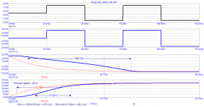
The rise time of the pulse signal for the output voltage slew rate test should be at least 3 times shorter than the rise time of the output voltage of the amplifier under test.
I used a 5 MHz LPF with a 48 ns rise time
For information: When testing high-speed op amps, use pulses with a rise time of less than 1 ns
Attachments
Petr, if you click on 'Quote' in the post you want to react to, the quoted post is automagically highlighted in your new post. Much easier to read.
Jan
Jan
- Home
- Amplifiers
- Solid State
- Bob Cordell's Power amplifier book