Michael
Why would anyone operate such an input stage in class A/B ?
Thanks
-Antonio
Precisely.
This class AB thing wrt the CFA front end has been raised as an objection quite a few times. This may be the case with IC opamps, where a few hundred micro amps is a useful power saving. In a discrete design you do not have these limitations.
So isn't it fair to specify cfa slew rate at say 40 percent of idle current ?
Thanks
-Antonio
". . . Why didnt you apply the cascode for the other CFA arm BTW ??"
That was a quick look see circuit. Only the front half of the bridge will drive the TIS, so I just tied the feedback buffer to the 15 v rails.
That was a quick look see circuit. Only the front half of the bridge will drive the TIS, so I just tied the feedback buffer to the 15 v rails.
So isn't it fair to specify cfa slew rate at say 40 percent of idle current ?
Thanks
-Antonio
Antonio, I think whatever the maximum that current can be delivered into the comp cap with an overdriven input signal should be the methodology. In VFA LTP's, the Miller cap current is limited by the LTP current. Of course you can mitigate this it=CV constraint with MIC, and in CFA's you can use a similar approach - See the Alexander Amplifier for an example, or more recently, either one of my two CFA efforts.
I highly doubt the veracity of this; I fail to appreciate how a "CFA" input stage that operates in class-AB can be inherently more linear than a current-mirror loaded LTP which operates in class-A.
Bonsai has aswerered this adequately but even in IC opamps the CFA input stage is designed as such that only when overdriven gets into real AB mode. They were not designed for use in overdriven state and I doubt anyone ever uses them as such.
Its better to look at this AB classification as a push pull operation type configuration similar to push pull classs A operation.
Michael, from your other posts I can deduce you are scholared in electronics, I dont doubt you understand these concepts and I for one cannot figure out why youre so negative about the CFA concept when clearly it is very useful, even for audio. One only needs to look at the spec sheets of opamps using these concepts to see that they offer improved performance. It becomes even more useful when creating VFB type circuits using CFA concepts like in Bonsai s circuit which combines the paticular benefits of each of these topologies.
.....I dont doubt you understand these concepts and I for one cannot figure out why youre so negative about the CFA concept when clearly it is very useful, even for audio. One only needs to look at the spec sheets of opamps using these concepts to see that they offer improved performance. It becomes even more useful when creating VFB type circuits using CFA concepts like in Bonsai s circuit which combines the paticular benefits of each of these topologies.
No doubt a "CFA" can be persuaded to perform adequetely if one works very hard at it. The fact remains, however, that for audio applications LTP based VFAs give superior performance with very little effort.
I don't think Bonsai's "CFA" offerings improve on the performance of well designed VFAs at all.
This class AB thing wrt the CFA front end has been raised as an objection quite a few times. This may be the case with IC opamps, where a few hundred micro amps is a useful power saving. In a discrete design you do not have these limitations.
Hi Bonsai,
My general inclination is to avoid circuits where the input stage is operated class AB. I think that there is adequate slew rate available with conventional topologies for audio purposes.
Cheers,
Bob
Yes, I absolutely agree with this as well. It's quite easy to bias up a CFA front end so that the output of the buffer remains in class A.
If you overdrive the input as I mentioned, then of course you can force the buffer to switch so that only one half is conducting. But, this is analogous to overdriving a mirror loaded LTP and forcing all the tail current into one half of the load.
If you overdrive the input as I mentioned, then of course you can force the buffer to switch so that only one half is conducting. But, this is analogous to overdriving a mirror loaded LTP and forcing all the tail current into one half of the load.
Last edited:
We have been around this CFA vs VFA thing quite a bit now Michael. I happen to think (and so do many others) that CFA's can bring a lot to audio amplifiers. However, unlike a few other people, I am absolutely agnostic on the topology and have designed, built and listened to both types. On the other hand, you seem obsessed with a few specifications where the VFA seems to excel in absolute numbers: distortion (only just) and PSRR. Have your listened to exemplars from either topology?
There is no correlation between perceived sound quality at 30 ppm and 10 ppm distortion. And the same applies at 300 ppm and 100 ppm.
Sonically, the CFA's I've built hold their own against the VFA's quite remarkably. And, anecdotal evidence from elsewhere also points to the fact that they in no way inferior on listening tests.
We have been around this CFA vs VFA thing quite a bit now Michael. I happen to think (and so do many others) that CFA's can bring a lot to audio amplifiers. However, unlike a few other people, I am absolutely agnostic on the topology and have designed, built and listened to both types. On the other hand, you seem obsessed with a few specifications where the VFA seems to excel in absolute numbers: distortion (only just) and PSRR. Have your listened to exemplars from either topology?
There is no correlation between perceived sound quality at 30 ppm and 10 ppm distortion. And the same applies at 300 ppm and 100 ppm.
Sonically, the CFA's I've built hold their own against the VFA's quite remarkably. And, anecdotal evidence from elsewhere also points to the fact that they in no way inferior on listening tests.

Stability issue in example amplifier, book page 63
Hi Bob,
when playing with one of your example amplifiers, I found an instability issue due to the lacking capacitor around the Vbe multiplier.
http://www.diyaudio.com/forums/solid-state/234408-stability-analysis-ef-output-stages.html
Maybe, you can add it in the second edition?
BR,
Matze
Hi Bob,
when playing with one of your example amplifiers, I found an instability issue due to the lacking capacitor around the Vbe multiplier.
http://www.diyaudio.com/forums/solid-state/234408-stability-analysis-ef-output-stages.html
Maybe, you can add it in the second edition?
BR,
Matze
It's the complementary common emitter stage in a "CFA" that operates in class AB and not the buffers.Yes, I absolutely agree with this as well. It's quite easy to bias up a CFA front end so that the output of the buffer remains in class A.
Sonically, the CFA's I've built hold their own against the VFA's quite remarkably. And, anecdotal evidence from elsewhere also points to the fact that they in no way inferior on listening tests.
As I have pointed out elsewhere there can be no perceived audible difference between a well designed so-called "CFA" and a well designed VFA.
However, the point is one of technical principal: VFAs are in general superior to "CFAs" in audio application.
Hi Bob,
when playing with one of your example amplifiers, I found an instability issue due to the lacking capacitor around the Vbe multiplier.
http://www.diyaudio.com/forums/solid-state/234408-stability-analysis-ef-output-stages.html
Maybe, you can add it in the second edition?
BR,
Matze
You should read the book more carefully, page 291 about the bias spreader bypass capacitor.
BR Damir
It's the complementary common emitter stage in a "CFA" that operates in class AB and not the buffers.

Nothing in the front end of this 15W CFA (input buffers, summers, TIS stage) runs in class AB. Everything is in class A.
Attachments
Last edited:
As I have pointed out elsewhere there can be no perceived audible difference between a well designed so-called "CFA" and a well designed VFA.
So why why all the anti CFA invective?
However, the point is one of technical principal: VFAs are in general superior to "CFAs" in audio application.
In general:-
6dB in distortion difference on a typical design. 10ppm is acheivable with CFA, 3-5ppm with a VFA.
CFA bandwidth typically wider than VFA
CFA slew rate and rise times better
PSRR - VFA is better
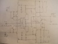
Not to complicate things , but I have found that the 'CFA' topology is quite friendly with using 'common mode error correction' via a common mode amplifier to modulate the source current that bias the input stage. Any stray difference in bias due to the feedback current is mitigated. I have played with this concept with both VFA and CFA input stages. I find in the CFA version that the common mode loop is easier to stabilize. Here is a basic sketch example of what I did. The common mode 'dependent CCS' current must be higher than the maximum change in 'error current' from the feedback voltage divider. This makes sure the IPS is always in class A, and that the actual change in current of the IPS is only that of what is required to drive the next stage. The global compensation is TMC ala Edmond S. & Cherry. You can criticize this approach it if you wish
 , I do not care because I know it works.😎 BTW, I have a special place in my heart for J-fets.
 I fear the day they are no longer made and no longer available.🙁
, but I have found that the 'CFA' topology is quite friendly with using 'common mode error correction' via a common mode amplifier to modulate the source current that bias the input stage. Any stray difference in bias due to the feedback current is mitigated. I have played with this concept with both VFA and CFA input stages. I find in the CFA version that the common mode loop is easier to stabilize. Here is a basic sketch example of what I did. The common mode 'dependent CCS' current must be higher than the maximum change in 'error current' from the feedback voltage divider. This makes sure the IPS is always in class A, and that the actual change in current of the IPS is only that of what is required to drive the next stage. The global compensation is TMC ala Edmond S. & Cherry. You can criticize this approach it if you wish, I do not care because I know it works.😎 BTW, I have a special place in my heart for J-fets. I fear the day they are no longer made and no longer available.🙁Attachments
Hi Bob,
when playing with one of your example amplifiers, I found an instability issue due to the lacking capacitor around the Vbe multiplier.
http://www.diyaudio.com/forums/solid-state/234408-stability-analysis-ef-output-stages.html
Maybe, you can add it in the second edition?
BR,
Matze
Hi Matze,
Thanks for bringing this to my attention. I always use a bypass capacitor with a bias spreader/Vbe multiplier, and the absence of that capacitor in the amplifier examples like those in Chapter 3 is a simplification of the circuit. I should not have taken that simplification liberty and allowed the possibility of confusion on a reader's part. I'll make sure that in the second edition I'll include the capacitor or at least clearly and explicitly mention in the text the need for it.
Thanks again for bringing this to my attention and I welcome any other feedback.
Cheers,
Bob
Hi Bob,
You might consider including calculations for your SOA protection circuits in your second edition. This would aid folk in designing their own protection circuits.
Secondly, you could show how designers may confirm and tweak their calculated SOA protection component values in SPICE, as well as simulating the effect of ambient temperature on the protection locus.
All this information is available in an article you can have by sending me mail.
- Home
- Amplifiers
- Solid State
- Bob Cordell's Power amplifier book