Something administrative: somebody asked me about a PCB for Bob's Distortion Magnifier, described in Linear Audio Volume 0. Unfortunately, I lost that message and don't remember the sender's name.
If you are that person please contact me.
jan didden
I asked here:
http://www.diyaudio.com/forums/soli...rdell-distortion-analyser-22.html#post2667327
Yet another insidious source of distortion
(continued from this post)
While fiddling with compensation caps in order to further improve the PSRR, I found another source of distortion. We know already that magnetic fields radiated by the power supply rails can have a serious impact on the distortion (see Bob's post). However, if the PSRR is inadequate, voltage fluctuation on the supply lines (as a result of half wave rectified currents in the OPS) may also degrade the performance. This is the electrical counterpart of magnetically induced distortion.
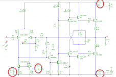
Please have a look at the example below and ignore C1 and C3 for the moment The PSRR of the negative supply rail is rather poor (38dB @ 10kHz). This is because the frequency compensation (TMC) is referenced to this rail (instead of gnd). With a perfect power supply (Ri=0) THD20=1.29ppm
If we increase Ri of the PSU by inserting a small 10mOhm resistor (see R17) in series with the positive supply rail, distortion is still 1.3ppm. Doing the same thing with the negative supply rail (see R18), distortion rises to 14ppm. More than ten times as much!
Clearly, this is a result of a poor PSRR. Of course we can filter the supply line. But strictly speaking, this doesn't improve the PSRR of the amp itself, rather the quality of the power supply. A more elegant (and cheaper) solution is the addition of two tiny caps: C1 and C3. Now the PSRR improves from 38 to 84dB. And the THD20? Well, it's back to 1.25ppm. Not that bad I would say.
Notice that, opposed to a previous version, I have added a second cap: C1. This one preserves the symmetry of the current mirror by equalizing the impedances in the emitter leads. Also notice that these caps have no effects on the (open loop) gain.
By the way, Douglas Self has already identified seven distinct sources of distortion. Should we call this one the 8th?
Cheers,
E.
Oh, one more thing: The TPC variant of this amp does 1.58ppm.
Who says that TPC is 'superior'?
(continued from this post)
While fiddling with compensation caps in order to further improve the PSRR, I found another source of distortion. We know already that magnetic fields radiated by the power supply rails can have a serious impact on the distortion (see Bob's post). However, if the PSRR is inadequate, voltage fluctuation on the supply lines (as a result of half wave rectified currents in the OPS) may also degrade the performance. This is the electrical counterpart of magnetically induced distortion.
Please have a look at the example below and ignore C1 and C3 for the moment The PSRR of the negative supply rail is rather poor (38dB @ 10kHz). This is because the frequency compensation (TMC) is referenced to this rail (instead of gnd). With a perfect power supply (Ri=0) THD20=1.29ppm
If we increase Ri of the PSU by inserting a small 10mOhm resistor (see R17) in series with the positive supply rail, distortion is still 1.3ppm. Doing the same thing with the negative supply rail (see R18), distortion rises to 14ppm. More than ten times as much!
Clearly, this is a result of a poor PSRR. Of course we can filter the supply line. But strictly speaking, this doesn't improve the PSRR of the amp itself, rather the quality of the power supply. A more elegant (and cheaper) solution is the addition of two tiny caps: C1 and C3. Now the PSRR improves from 38 to 84dB. And the THD20? Well, it's back to 1.25ppm. Not that bad I would say.
Notice that, opposed to a previous version, I have added a second cap: C1. This one preserves the symmetry of the current mirror by equalizing the impedances in the emitter leads. Also notice that these caps have no effects on the (open loop) gain.
By the way, Douglas Self has already identified seven distinct sources of distortion. Should we call this one the 8th?
Cheers,
E.
Oh, one more thing: The TPC variant of this amp does 1.58ppm.
Who says that TPC is 'superior'?
Attachments
If we are accidentaly already using (at higher PSU voltage, or high beta and low Vce input LTP transistors) cascoded input LTP, so conecting C4 to junction of colector T1 and emitor of cascode transistor (not to colector Q2) will do the same job in improving negative rail PSRR as added capacitors C1and C3.
Last edited:
Hi BV,
You are right. There are more ways to improve the PSRR. However, my point is that we should be aware of this kind of distortion and take appropriate measures to avoid it, one way or the other way.
Cheers,
E.
You are right. There are more ways to improve the PSRR. However, my point is that we should be aware of this kind of distortion and take appropriate measures to avoid it, one way or the other way.
Cheers,
E.
I found another paper (from 1952!) that I'm sure you guys will be interested in. About transient response, ringing, stability and the role of feedback. From a Mr. Roddam.
Top left reference here: Historical Library
jan
Top left reference here: Historical Library
jan
Last edited:
There is a very nice AES paper by Harry Dymond et al discussing the technique you show BV.
Question: how can the PSRR on resistively loaded LTP's be improved?
Question: how can the PSRR on resistively loaded LTP's be improved?
That's exactly the way I did the thermal comp in this amp proto-type. In this case the outputs are mosfets, the SOT-23 transistors are PCB mounted under the drain pins on a pad that allows me to move it about 5mm closer or further from the plastic case to adjust for best tracking. Oh yeah, and it works nicely.🙂
The Eagle drawing example below is from my next amp, here they are SOT-323, or SOT-23 mini, 2mm X 1.2mm. The TO-220 output device mounts horizontal to the PCB, the gate and source pins are shorter, the drain pin extends over top and contacts the SOT-323.
This is how i do it in my Ovation 250w amp. But, i need to caution you if you are using a triple!
In my case, i have the drivers and output devices (5 per rail MJL21193/4) on the heatsink, but the pre drivers on separate stand alone heatsinks on the main PCB. Initially I had terrible results, and Iq was all over the place. I put a fan on the amp and Iq went down. I turned the fan off, and Iq went up.
Trick to solve the problem: make sure the outputs, driver and pre drivers are all at similar temperatures. In my case, the pre drivers ran very hot, and so heated up. The sensor transistor actually was actually tracking the heatsink and the pre drivers were not included. I reduced the pre driver current, the their temp dropped and viola, problem solved. On my current design in prgress, the pre drivers are on the main hestsink as well. I still stuck with a BC847 sensor thermally coulpled with a glob of h/sink grease to one of he ouput devices collector leads. Completion and write up still some months away though!
Cdom PSRR compensation is shown by Self, "Negative Supply-Rail Rejection" p290+ in the 5th ed of his amplifier book (and he's up to 11 in his numberd distortions)
and one of my favorite references:
“A General Relationship Between Amplifier Parameters, And Its Application to PSRR Improvement” E Sackinger, J Groette, W Guggenbuhl, IEEE Trans CAS vol 38, #10 10/83 pp 1171-1181
http://citeseerx.ist.psu.edu/viewdoc/summary?doi=10.1.1.27.6813 - clik on the cached PDF icon
treats the problem, shows several options to improve PSRR
compensating for 2-pole TMC network can be done by connecting to cascode or duplicating the network and connecting to gnd and mirror or cascode
Last edited:
distortion #12
Hi jcx,
I know this (of course), but I wouldn't call his methods 'compensation'.
The 1st method is simply a brute force RC filter in the power supply line. Thus improving the power supply, not the PSRR.
The 2nd method, tying Cdom to the cascode, isn't a compensation either, rather moving the reference to a quieter point.
Furthermore, as far as I know, Self didn't describe the effect on distortion figures as shown by me (correct me if I'm wrong).
So why quoting him anyhow?
Okay, apparently I'm behind (in EW+WW, August 1993, he mentioned only seven). So lets call it distortion #12
Indeed, this document shows also this type of compensation, though in it's most simple form (fig. 6).
Sure, that was my very first idea as well. But in case of TMC (or TPC) you don't need an exact duplicate. One simple cap (between the current mirror input and ground) will do as well. Besides, because of several side effects, you will need a slight higher cap anyhow. So an exact copy makes no sense.
As Samuel Groner pointed out, this method affects the bandwidth (a little bit). It also disturbs the balance of the current mirror (a little bit). The compensation as shown in post 2162 doesn't suffer from these (not so gross) side effects.
BUT... I don't care which method is best and who invented it. As a matter of fact, all known methods are rather obvious, not worth a patent.
My point is that I was rather surprised by the relative large impact on the distortion of a non zero (10mOhms) source impedance of the PSU.
Cheers,
E.
Cdom PSRR compensation is shown by Self, "Negative Supply-Rail Rejection" p290+ in the 5th ed of his amplifier book
Hi jcx,
I know this (of course), but I wouldn't call his methods 'compensation'.
The 1st method is simply a brute force RC filter in the power supply line. Thus improving the power supply, not the PSRR.
The 2nd method, tying Cdom to the cascode, isn't a compensation either, rather moving the reference to a quieter point.
Furthermore, as far as I know, Self didn't describe the effect on distortion figures as shown by me (correct me if I'm wrong).
So why quoting him anyhow?
(and he's up to 11 in his numberd distortions)
Okay, apparently I'm behind (in EW+WW, August 1993, he mentioned only seven). So lets call it distortion #12
and one of my favorite references:
“A General Relationship Between Amplifier Parameters, And Its Application to PSRR Improvement” E Sackinger, J Groette, W Guggenbuhl, IEEE Trans CAS vol 38, #10 10/83 pp 1171-1181
CiteSeerX — A General Relationship between Amplifier Parameters and its Application to PSRR Improvement - clik on the cached PDF icon
treats the problem, shows several options to improve PSRR
Indeed, this document shows also this type of compensation, though in it's most simple form (fig. 6).
compensating for 2-pole TMC network can be done by just duplicating the network and properly connecting to gnd or rail and mirror or cascode
Sure, that was my very first idea as well. But in case of TMC (or TPC) you don't need an exact duplicate. One simple cap (between the current mirror input and ground) will do as well. Besides, because of several side effects, you will need a slight higher cap anyhow. So an exact copy makes no sense.
As Samuel Groner pointed out, this method affects the bandwidth (a little bit). It also disturbs the balance of the current mirror (a little bit). The compensation as shown in post 2162 doesn't suffer from these (not so gross) side effects.
BUT... I don't care which method is best and who invented it. As a matter of fact, all known methods are rather obvious, not worth a patent.
My point is that I was rather surprised by the relative large impact on the distortion of a non zero (10mOhms) source impedance of the PSU.
Cheers,
E.
Edmond,
yes, I am really surprised at the amount of distortion introduced my such a small rail Z.
JCX - thanks for posting the link
yes, I am really surprised at the amount of distortion introduced my such a small rail Z.
JCX - thanks for posting the link

I think TMC is superior. So do Baxendall, Stuart and even Self.
Cheers,
Bob
Baxandal has never said he prefers TMC to TPC, and , I think, neither has Self pronounced himself on the issue. So, speak for yourself.
TMC can never be superior to TPC, for sound technical reasons.
However I concede that you're entitled to your opinion.
Baxandal has never said he prefers TMC to TPC, and , I think, neither has Self pronounced himself on the issue. So, speak for yourself.
TMC can never be superior to TPC, for sound technical reasons.
However I concede that you're entitled to your opinion.
Hi Mike,
Do you read Linear Audio? Did you read Self's article on what was essentially TMC? You should. I think that most people reading his article there would conclude that he is a proponent of it.
I don't think you have ever articulated your assertion that TMC can never be superior to TPC, nor ever shown your assertion to be true for several cases through simulation. Saying something with the word NEVER is a pretty strong assertion. Your incessant handwaiving does not constitute "sound technical reasons".
If you prefer TPC to TMC that is fine, and you may even have good reason. But please don't make absolute generalized assertions like you are prone to do without a very solid basis.
I see that you feel strongly about this issue, so I suggest you start a new thread titled something like "TPC vs TMC" where you can better articulate you sound technical reasons and show real simulations to make your point.
In the meantime, anyone here can go back and look at the original TMC discussion and judge for themselves whether you aguments then were solid and whether you answered questions posed directly to you about your assertions.
Cheers,
Bob
PCB
Hi there,
Not to clutter this thread I posted a pdf version of my pcb in my own thread.
It would be nice to have some feedback...
Greetz,
Olivier
Hi there,
Not to clutter this thread I posted a pdf version of my pcb in my own thread.
It would be nice to have some feedback...
Greetz,
Olivier
Hi all
The first pic below shows a simple front-end with Cdom compensation and an added capacitor (Cpsrr) to fix the PSRR.
Now, IIRC, Edmond showed a while ago that moving Cpsrr from the collector to the emitter of Q4, as shown in the second pic, improves performance.
I'm wondering if moving Cdom from the collector to the emitter of Q3 would also result in an improvement since this avoids adding the small but very non-linear signal voltage at the base of Q3 to the VAS output.
Since the local feedback current through Cdom is now being applied to a low impedance node, stability may be improved as well because the VAS output impedance will be lower at high frequencies.
Connecting Cdom this way should also do away with the need for the 3'rd capacitor that Edmond recently added, I think... ...
...
As an aside, I think stabilizing Q5's collector voltage as shown is a good idea. It provides overcurrent protection for Q5 and also prevents Q5's Ccb adding to the PSRR problem.
Any thoughts on this?
Cheers - Godfrey
P.S. I'm being lazy and haven't actually run any sims, as you might have guessed from the lousy component choices shown.😀
The first pic below shows a simple front-end with Cdom compensation and an added capacitor (Cpsrr) to fix the PSRR.
Now, IIRC, Edmond showed a while ago that moving Cpsrr from the collector to the emitter of Q4, as shown in the second pic, improves performance.
I'm wondering if moving Cdom from the collector to the emitter of Q3 would also result in an improvement since this avoids adding the small but very non-linear signal voltage at the base of Q3 to the VAS output.
Since the local feedback current through Cdom is now being applied to a low impedance node, stability may be improved as well because the VAS output impedance will be lower at high frequencies.
Connecting Cdom this way should also do away with the need for the 3'rd capacitor that Edmond recently added, I think...
...As an aside, I think stabilizing Q5's collector voltage as shown is a good idea. It provides overcurrent protection for Q5 and also prevents Q5's Ccb adding to the PSRR problem.
Any thoughts on this?
Cheers - Godfrey
P.S. I'm being lazy and haven't actually run any sims, as you might have guessed from the lousy component choices shown.😀
Attachments
Last edited:
Compensation
Hi Godfrey,
Tying Cdom to the emitter of the CM is a very interesting idea. So I immediately simmed it. Regrettable, the distortion increases.
In order to exclude other distortions, which could easily mask the improvement, I've used ideal components for the IPS and OPS, and a Hawksford cascode for the VAS, but to no avail.
Next, I've replaced the simple CM by a Improved Wilson Fudh current mirror. Again, to no avail. Tying Cdom directly to the VAS input still gives better results.
Clearly, I'm overlooking something. If time permits, I will try to figure out what's exactly going on.
Cheers,
E.
Cpsrr connected from Emitter to supply rail is very commonly used by British amplifier designers.
It is found in Crimson and JLH and Sugden amps, going back to the 70's/80's.
It is found in Crimson and JLH and Sugden amps, going back to the 70's/80's.
Cpsrr connected from Emitter to supply rail is very commonly used by British amplifier designers.
It is found in Crimson and JLH and Sugden amps, going back to the 70's/80's.
Youre right Andrew, in the case of JLH he never explains the reason for it though. Its used the way Edmond showed it and unlike Godfrey s first schematic.
Hi all
The first pic below shows a simple front-end with Cdom compensation and an added capacitor (Cpsrr) to fix the PSRR.
Now, IIRC, Edmond showed a while ago that moving Cpsrr from the collector to the emitter of Q4, as shown in the second pic, improves performance.
I'm wondering if moving Cdom from the collector to the emitter of Q3 would also result in an improvement since this avoids adding the small but very non-linear signal voltage at the base of Q3 to the VAS output.
Since the local feedback current through Cdom is now being applied to a low impedance node, stability may be improved as well because the VAS output impedance will be lower at high frequencies.
Connecting Cdom this way should also do away with the need for the 3'rd capacitor that Edmond recently added, I think...
As an aside, I think stabilizing Q5's collector voltage as shown is a good idea. It provides overcurrent protection for Q5 and also prevents Q5's Ccb adding to the PSRR problem.
Any thoughts on this?
Cheers - Godfrey
P.S. I'm being lazy and haven't actually run any sims, as you might have guessed from the lousy component choices shown.😀
I'm about to publish a bookzine with collected papers from Wireless World, which also includes an unpublished personal letter from Peter Baxandall, 1995. In the letter, commenting on Doug Self's amplifier series, he discusses TMC and gives some reasons why connecting Cdom to Vout often leads to stubborn oscillations. In one of his hand-written diagrams (the letter is typewriter-written with hand drawn illustrations) he connects the resistor in the TMC to Vout, which I hadn't seen before.
Samuel Groner came up with an early reference for a TMC patent, from 1979 (Hitachi, Kunio Seki, US pat 4145666), although there is no indication that Peter was aware of the patent.
jan didden
- Home
- Amplifiers
- Solid State
- Bob Cordell's Power amplifier book