Hi Walt,
Thank you very, very much for this great review and the time and effort you obviously put into it. Such a review is especially meaningful coming from you, as one who is not only a well-known and accomplished author, but one who has been a giant in analog design for 40 years.
You have given me an early Christmas present!
Thanks!!
Bob
I tickled that you liked it so much Bob. It is a worthwhile book, and I was simply trying to bring out some of the details that distinguish it from others.
Thanks also to janneman and jackinnj for chiming in on my writeup.
Walt
I tickled that you liked it so much Bob. It is a worthwhile book, and I was simply trying to bring out some of the details that distinguish it from others.
Thanks also to janneman and jackinnj for chiming in on my writeup.
Walt
Hi Walt,
Now that I have your ear... YGM 😉
jan didden
Hi,
emitter degeneration greatly improves the generally very poor Vbe / Ic proportionality, stabilizes Vbe and the operating point, but degrades the switching performance, increasing crossover distortion.
Rafael L and Bonsai,
a high current gain comes at the cost of considerably increased distortion. Your simulations cannot say anything about what happens dynamically, all you get is lot of false and misleading data.
In the output stage (EF), no degeneration would give best results, but thermally impossible solution.
a high current gain comes at the cost of considerably increased distortion. Your simulations cannot say anything about what happens dynamically, all you get is lot of false and misleading data.
Large signal conditions can be set before launching a sim..
Anyway, when an amp is simulated at high power, it s no
more a small signal analysis, by the definition...
Rafael L and Bonsai,
a high current gain comes at the cost of considerably increased distortion. Your simulations cannot say anything about what happens dynamically, all you get is lot of false and misleading data.
WuYit,
Unfortunately it's not just the crossover distortion the problem of an output stage, you have other sources of distortion as high consumption of FT an output stage EF. A high polarization is detrimental if gain and FT is limited in TRs...
Wouldn't it be a good idea to bypass the base stoppers with small inductors? E.g. 10uH in parallel with 10R for an output device. That should improve thermal stability and distortion without hurting RF stability. The little ones that look like resistors and cost peanuts would be ideal.
I've never seen this done, though. Am I missing something?
Hi Godfrey,
Bypassing the base stoppers with an inductor is not completely unreasonable, but the details are important. First a ferrite bead or a ferrite-based inductor must not be used, as there are always concerns about the effect on sound quality when beads or ferrites are used.
It is also cruscial that they not be in a position to pick up magnetic fields that could in some cases possibly make things worse. Such magnetic fields could be created by the collector or emitter wiring of the associated power transistor, or by power rail wiring.
It may also be fairly important to have very small parasitic capacitance in the inductor. The base stoppers like to be very close to the base terminal and look really resistive up to very high frequencies.
I have not tried the use of inductors for bypassing base stoppers. Instead, I try to use the smallest reasonable base stopper that will guarantee no oscillation under worst conditions. The better the layout and bypassing, the smaller base stopper can be used in general. The use of power supply zobel networks to quash any tendency to resonance can also be helpful. Finally as with power MOSFETs, base Zobel networks can be considered. These networks go from the base to ground, or in some cases, better, base to collector. These tend to lower the Q of the collector-base capacitance, which is often involved in creating the parasitic oscillator topology. Any additional current drive needed to drive the Zobel networks at high frequencies must be considered, however.
In Triples, it also sometimes helps to employ modest base stoppers in the driver transistors as well.
Cheers,
Bob
Finally as with power MOSFETs, base Zobel networks can be considered. These networks go from the base to ground, or in some cases, better, base to collector. These tend to lower the Q of the collector-base capacitance, which is often involved in creating the parasitic oscillator topology. Any additional current drive needed to drive the Zobel networks at high frequencies must be considered, however.
In Triples, it also sometimes helps to employ modest base stoppers in the driver transistors as well.
Cheers,
Bob
Hi Bob,
I noticed in simulation that output EF or Triple with BJT lose a considerable phase margin with a capacitive load, believe this is related to the high impedance output EF in open loop. I do not know which is really the problem, if is a simple pole formed by the Miller effect, or inductive output, forming a complex pole (Q) with a capacitive load? Base stoppers no are helping to alleviate the problem...
Thanks
Power rail bypassing
Hi Bob,
RE:
"The use of power supply zobel networks to quash any tendency to resonance can also be helpful."
Would it be just as effective to bypass from rail to rail rather than rail to ground?
Sometimes it's more convenient to do this.
David.
Hi Bob,
RE:
"The use of power supply zobel networks to quash any tendency to resonance can also be helpful."
Would it be just as effective to bypass from rail to rail rather than rail to ground?
Sometimes it's more convenient to do this.
David.
Hi Bob
A copy of your book has come my way, and I have a question about the section on Inclusive (or if you prefer, Transitional) compensation in power amplifiers. You say on p182 that the idea was proposed by Cherry, implying that he proposed it first. I am interested in sorting out the history of this technique, and I would be glad if you could give me a reference for this.
You might be aware of my article on the subject in Linear Audio Vol 0, which gives some measurements on a real amplifier using this compensation method. I would be glad to hear your comments.
TMC
Hi Douglas,
If you don't mind, I also like to respond to your questions.
As for 'output inclusive compensation' (being NOT the same as TMC), it was proposed by Cherry in:
1. E.M. Cherry, "Nested Differentiating Feedback Loops in Simple Audio Power Amplifiers", JAES, May, 1982, pp. 295-302, (fig. 11 & 14).
2. E.M Cherry, "Ironing Out Distortion", EW+WW, Jan. 1995, pp.14-20 (fig. 2),
3. E.M Cherry, "Ironing Out Distortion", EW, July, pp. 577-582 (fig. 6)
And probably many more papers.
Would you be glad to hear also my comments? 😉
1. http://www.diyaudio.com/forums/soli...erview-negative-feedback-303.html#post2355163
2. http://www.diyaudio.com/forums/soli...erview-negative-feedback-309.html#post2366903
Cheers,
E.
Hi Bob
A copy of your book has come my way, and I have a question about the section on Inclusive (or if you prefer, Transitional) compensation in power amplifiers. You say on p182 that the idea was proposed by Cherry, implying that he proposed it first. I am interested in sorting out the history of this technique, and I would be glad if you could give me a reference for this.
Hi Douglas,
If you don't mind, I also like to respond to your questions.
As for 'output inclusive compensation' (being NOT the same as TMC), it was proposed by Cherry in:
1. E.M. Cherry, "Nested Differentiating Feedback Loops in Simple Audio Power Amplifiers", JAES, May, 1982, pp. 295-302, (fig. 11 & 14).
2. E.M Cherry, "Ironing Out Distortion", EW+WW, Jan. 1995, pp.14-20 (fig. 2),
3. E.M Cherry, "Ironing Out Distortion", EW, July, pp. 577-582 (fig. 6)
And probably many more papers.
You might be aware of my article on the subject in Linear Audio Vol 0, which gives some measurements on a real amplifier using this compensation method. I would be glad to hear your comments.
Would you be glad to hear also my comments? 😉
1. http://www.diyaudio.com/forums/soli...erview-negative-feedback-303.html#post2355163
2. http://www.diyaudio.com/forums/soli...erview-negative-feedback-309.html#post2366903
Cheers,
E.
Last edited:
Since we are talking about Edmond's TMC this link can be very informative, too.
To TMC or not to TMC
Cheers
To TMC or not to TMC
Cheers
Last edited:
Edmond,
would it be possible to just give a concise account of what TMC is about, please? Reduced distortion compared to what? I`m not even familiar with the abbreviation terms used.
would it be possible to just give a concise account of what TMC is about, please? Reduced distortion compared to what? I`m not even familiar with the abbreviation terms used.
Hi Bob
A copy of your book has come my way, and I have a question about the section on Inclusive (or if you prefer, Transitional) compensation in power amplifiers. You say on p182 that the idea was proposed by Cherry, implying that he proposed it first. I am interested in sorting out the history of this technique, and I would be glad if you could give me a reference for this.
You might be aware of my article on the subject in Linear Audio Vol 0, which gives some measurements on a real amplifier using this compensation method. I would be glad to hear your comments.
Hi Doug,
Thanks for buying my book and I hope you enjoy the read.
To the best of my knowledge, output inclusive Miller compensation was first proposed by Ed Cherry, and I believe Edmond has provided the relevant references. I was remiss in my book to fail to cite a reference to Ed Cherry's work there. I'll fix that in my second edition.
Bear in mind that not all inclusive compensation is Transitional Miller Compensation (TMC). Cherry's was just inclusive of the output stage and had no aspect of transition to straight Miller compensation at high frequencies. I don't think this was one of Ed's best proposals because of his failure to address the stability problem created by so much high-frequency feedback around the output stage.
I believe that I may have been the first to use what you might call input inclusive compensation in an audio amplifier. This I called Miller Input Compensation (MIC), and I used it in my 1984 MOSFET power amplifier with error correction. It was simply Miller compensation that was brought back to the input of the input stage instead of the the input of the VAS. This included the input stage in the compensation feedback loop and greatly increased its dynamic range and freed the amplifier from the usual constraints governing slew rate.
Although I have been told that Baxandall came up with the TMC idea, I have never seen a published reference to it by him. As a prolific writer, I would have expected to see some sort of publication from him describing it. Do you have such a public reference? In reality, I don't think the technique became known generally until Edmond popularized it, named it and demonstrated the distortion improvement it could yield at such a small expense.
I believe that numerous folks here at DIYaudio have built TMC amplifiers over the last couple of years, and your data presented in the Linear Audio article confirms the value of this technique. I believe you showed an improvement of about 3:1 at high frequencies.
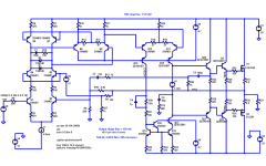
Edmond convinced me about three years ago that TMC was competitive with Hawksford Error Correction (HEC) in providing very low distortion, yet at a much lower cost. About three years ago I simulated a version of my MOSFET power amplifier using TMC instead of HEC and got THD-20 below 0.001% out to 200 kHz analysis bandwidth. That design, shown below, combined TMC with MIC. The TMC inner loop was tapped from the predriver so as not to overly load the VAS. With the VAS output node unconnected to the Miller feedback, a simple R-C shunt was added to the VAS output node to retain compensation loop stability.
Cheers,
Bob
Attachments
...
I believe that I may have been the first to use what you might call input inclusive compensation in an audio amplifier. This I called Miller Input Compensation (MIC), and I used it in my 1984 MOSFET power amplifier with error correction. It was simply Miller compensation that was brought back to the input of the input stage instead of the the input of the VAS. This included the input stage in the compensation feedback loop and greatly increased its dynamic range and freed the amplifier from the usual constraints governing slew rate.
....
Cheers,
Bob
I believe that C2 in this schematic from 1973 is what you would call MIC:
http://www.swtpc.com/mholley/RadioElectronics/Dec1973/RE_Dec_1973_pg44.jpg
I've not forgotten about the Citation 12 sims ... just have been very busy.
Last edited:
I believe that C2 in this schematic from 1973 is what you would call MIC:
http://www.swtpc.com/mholley/RadioElectronics/Dec1973/RE_Dec_1973_pg44.jpg
I've not forgotten about the Citation 12 sims ... just have been very busy.
Hi Pete,
I think you are right!
Thanks,
Bob
- Home
- Amplifiers
- Solid State
- Bob Cordell's Power amplifier book