Howdy,
I recently gave my view on this in the other thread:
The bipolar transistor output stage "optimal" bias theory in conjunction with Gm-doubling distortion constitutes just one of many perplexing findings made by D. Self. Since Gm-doubling distortion appears in the class A overlap region, he prescribes a low operating point. Gm-doubling distortion is subjectively mild compared to the highly objectionable switching and crossover distortion (Gm-doubling distortion is part of the crossover distortion). Rather the scanty Gm near cutoff that causes substantial distortion, particularly low level input signals being severely distorted or not amplified at all. A low operating point makes Gm vary wildly with current and temperature. Also, the load resistance limits the transconductance.
Transition characteristics are device specific, why would a certain voltage drop on emitter resistor generally signify an "optimal" quiescent current?
Output stages should be class A biased for normal listening levels.
Hi WuYit,
The optimal output stage biasing theory is not a finding by Doug Self. Although he was one of the people who brought more attention to it, the matter was understood decades before, going back at least to Barny Oliver of HP. Indeed, the origin of the 26 mV emitter resistor drop goes back to Barny. I'm not sure, but it may be the case that Self coined the term gm doubling in connection with BJT output stages - the dual of "transconductance droop" that I had coined in 1983 in conjunction with MOSFET output stages.
You are correct in that gm doubling distortion is preferable to class B notch distortion. The 26 mV number derives from BJT device characteristics (kT/q), but is strictly valid for ideal BJT devices. The number will be slightly different as a result of ohmic emitter and base resistances, for example.
Cheers,
Bob
Hi Bob
I also noticed other optimization to output EF in circuit D.Self:
The first is the bias of the drivers, above 10 mA begins to increase THD (also to triple Darligton output). The second were the base stopper, the values of 100 Ohms, not been established for local oscillation, but to reduce the THD, I believe it's VAS not face a capacitive load and base stopper minimizes the problem. Decline in the value of base stopper increase THD, but this only for simple EF and not triple.
Hi Bob
I also noticed other optimization to output EF in circuit D.Self:
The first is the bias of the drivers, above 10 mA begins to increase THD (also to triple Darligton output). The second were the base stopper, the values of 100 Ohms, not been established for local oscillation, but to reduce the THD, I believe it's VAS not face a capacitive load and base stopper minimizes the problem. Decline in the value of base stopper increase THD, but this only for simple EF and not triple.
Hi Rafael,
Can you point me to some pages in Self's book where this is located (5th Edition? Other Edition?). That way I would be in a better position to comment on it.
Cheers,
Bob
Bob, there is no mention about this in Book D.Self, These observations, I made simulator with the circuit (Blameless), which is well optimized in THD.
I noticed that the base stopper in driver, reduces THD at very low levels, perhaps this is reason for him not to mention triple output, only for powerful amplifiers (3th edition).
Another thing that is not mentioned in the book, does not reduce THD if an output EF is biased in class A, so all circuits D.Self in Class A have only output CPF.
I noticed that the base stopper in driver, reduces THD at very low levels,
Really. Usually opposite is truth.
Andrew,
I'm with Bob on this. Recently I did a diamond buffer with three output pairs, 150W, and am now using Iq of 120mA for each pair with 0R15. There is no global fb in this amp, so that is a very good reason to drive down the Re since it impacts on the Zout.
Amp is quite stable at this rating, and Iq quite consistent.
In my global fb amps with more conventional DEF output stages I use 0.47R with good results, absolutely.
Hugh
Wouldn't it be a good idea to bypass the base stoppers with small inductors? E.g. 10uH in parallel with 10R for an output device. That should improve thermal stability and distortion without hurting RF stability. The little ones that look like resistors and cost peanuts would be ideal.
I've never seen this done, though. Am I missing something?
I've never seen this done, though. Am I missing something?
Really. Usually opposite is truth.
Some time ago made the simulation, I not remember the models. I'm referring to base stopper in Driver and not in output devices, the effect of capacitance is higher with TRs less gain (Ex: MJE340/350 and BD139/140)
Bias
Driver 5mA (BD139/140)
Output 110mA (RE 0,22)
THD 20 Khz
0,024%- base stopper = 1 Ohm
0,0042%- base stopper = 10 Ohm
0,006%- base stopper = 100 Ohm
"I also noticed other optimization to output EF in circuit D.Self:
The first is the bias of the drivers, above 10 mA begins to increase THD (also to triple Darligton output). The second were the base stopper, the values of 100 Ohms, not been established for local oscillation, but to reduce the THD, I believe it's VAS not face a capacitive load and base stopper minimizes the problem. Decline in the value of base stopper increase THD, but this only for simple EF and not triple."
I also observed this.
The problem is if you increase the driver or pre-driver standing current you change the Voltage drop across the output stage emitter degen resistors - which of course leads to distortion.
Re-adjust your Vbe spreader and your distortion will drop back to the lower value you observed when you ran the driver/pre-driver at lower standing current.
Wouldn't it be a good idea to bypass the base stoppers with small inductors? E.g. 10uH in parallel with 10R for an output device. That should improve thermal stability and distortion without hurting RF stability. The little ones that look like resistors and cost peanuts would be ideal.
I've never seen this done, though. Am I missing something?
Crown did this in there Macro Tech series, but not necessarily on the output transistors.
They used a parallel LCR.
David.
Attachments

Last edited:
Wouldn't it be a good idea to bypass the base stoppers with small inductors? E.g. 10uH in parallel with 10R for an output device. That should improve thermal stability and distortion without hurting RF stability. The little ones that look like resistors and cost peanuts would be ideal.
I've never seen this done, though. Am I missing something?
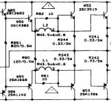
Hi, take a look at this HK OPS.
Edit: And many thanks to Bob Cordell for your nice book!
Attachments
Last edited:
I am attaching a PDF file with some comments on Bob Cordell's book. Hope they are helpful.
Walt Jung
Very nice Walt, thanks for that!
jan didden
I am attaching a PDF file with some comments on Bob Cordell's book. Hope they are helpful.
Walt Jung
Hi Walt,
Thank you very, very much for this great review and the time and effort you obviously put into it. Such a review is especially meaningful coming from you, as one who is not only a well-known and accomplished author, but one who has been a giant in analog design for 40 years.
You have given me an early Christmas present!
Thanks!!
Bob
Bonsai,
What is the mechanism of that distortion?The problem is if you increase the driver or pre-driver standing current you change the Voltage drop across the output stage emitter degen resistors - which of course leads to distortion.
Andrew,
I'm with Bob on this. Recently I did a diamond buffer with three output pairs, 150W, and am now using Iq of 120mA for each pair with 0R15. There is no global fb in this amp, so that is a very good reason to drive down the Re since it impacts on the Zout.
Amp is quite stable at this rating, and Iq quite consistent.
In my global fb amps with more conventional DEF output stages I use 0.47R with good results, absolutely.
Hugh
Hi Hugh,
Good points. RE=0.15 is fine as long as good attention is paid to thermal management and good output transistors are used without resort to overly-large base stopper resistors. Good layout and good power supply bypassing can reduce the needed value for base stopper resistors.
One thing I like to do in the case of a Locanthi Triple output stage is to put some R-C power supply bypassing between the main rail and the rail for the driver, and from the rail for the driver to the rail for the pre-driver. These can be low-impedance, low resistance R-C networks that do not drop much DC voltage at all (less than a volt) and provide good loss at high frequencies. As a bonus, the low-impedance of these networks acts like a Zobel network for the rail feeding the network, damping out any tendency toward resonance in the rails.
Cheers,
Bob
Andrew,
I'm with Bob on this. Recently I did a diamond buffer with three output pairs, 150W, and am now using Iq of 120mA for each pair with 0R15. There is no global fb in this amp, so that is a very good reason to drive down the Re since it impacts on the Zout.
Hello Hugh,
I built one-pair OL CFP diamond buffer amplifier in 2002, with 0R1 Re resistors and 1.3A idle current. I redesigned it in 2007, again with 0R1, and same idle current - but more pairs. Also, stable without any problems.
Regards,
"I also noticed other optimization to output EF in circuit D.Self:
The first is the bias of the drivers, above 10 mA begins to increase THD (also to triple Darligton output). The second were the base stopper, the values of 100 Ohms, not been established for local oscillation, but to reduce the THD, I believe it's VAS not face a capacitive load and base stopper minimizes the problem. Decline in the value of base stopper increase THD, but this only for simple EF and not triple."
I also observed this.
The problem is if you increase the driver or pre-driver standing current you change the Voltage drop across the output stage emitter degen resistors - which of course leads to distortion.
Re-adjust your Vbe spreader and your distortion will drop back to the lower value you observed when you ran the driver/pre-driver at lower standing current.
Yes is correct, but I always did Re-adjust VBE for the output TRs in optima polarization.
The optima polarization is not always reduce THD (%) compared to under biased, but reduces the crossover distortion of high harmonic have to look the FTT Graph.
- Home
- Amplifiers
- Solid State
- Bob Cordell's Power amplifier book