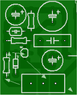
In light of this , would (below 1) be okay ? Or would a shielded cable be better.
Purple wire (NFB L/R) only crosses low imp. areas. Rails are at the sides (orange/red). BTW , that is the TMC'ed "bobamp" (or blameless).
OS
Hi ostripper,
Its a little hard for me to see exactly what is what. These may be dumb questions on my part. What is "cap mux". It looks like the input/driver board is separate and perpendicular to the output board. Is that right?
In the context of a single-board amplifier, I would generally try to run the FB line as a trace, perhaps guarded. On a two-board design, I would be inclined to run it as a shielded cable with one end of the shield connected to quiet ground. I would probably place a 100 ohm resistor in series with the output signal before it enters the center conductor of the shielded cable for short-circuit protection if nothing else. Then the NFB resistor would be at the other end of the shielded cable, near the input stage.
BTW, if your NFB resistor is 39k, this looks a bit high for noise and maybe even HF considerations. This would make the feedback shunt resistor on the order of 1-2k, making the impedance there a bit high. That node on the input LTP likes to be fairly low impedance. I often use a feedback resistor on the order of 4k-10k in many designs, even though this makes it necessary to use higher wattage resistors in the FB network. This, of course, is more practical in designs that use DC servos, else in some designs the NFB shunt capacitor can become rather large.
Cheers,
Bob
I would think the best approach is to place the junction of the feedback resistors (upper and lower arms i.o.w.) right at the inverting input. If you have any length of trace between the junction and the inverting input this can pick up noise or EMI (capacitively or inductively coupled), it will be amplifed by the full loop gain of the amplifier. A similar train of thought applies to the input filter circuit on the non-inverting input. In this case, noise pickup between the output of the filter and the input proper is amplified by the closed loop gain of the amplifer. All in all, very ugly stuff if you are shooting for a low noise design.
cap mux = cap multiplier i would think
Mux is a term usually used as short form for multiplexer. It seems confusing seeing this acronym used in context with an amplifier.
David.
i realize that, but i am also aware of the existence of capacitance multipliers, could be wrong, but placement would seem consistent also as is a pretty small pcb
Last edited:
i realize that, but i am also aware of the existence of capacitance multipliers, could be wrong, but placement would seem consistent also as is a pretty small pcb
I realized after posting this that Ostripper likes to include multiple compensation schemes on his boards which he can switch between for comparison. That's probably what the cap mux is.
David.
Mux is a term usually used as short form for multiplexer. It seems confusing seeing this acronym used in context with an amplifier.
David.
I agree...widely used in telecoms along with "demux" for demultiplexer.
Hi Bob,
Good to bump into you at the Montreal Audio show - was it in front of the MBL room???
On to my question - I'd like to try building up a SS amp to directly power some electrostatic panels. Let's say with rail voltages upwards of plus/minus 500 volts or more. Possible or not???
Charles
Do you need push pull drive as in this configuration?
http://users.forthnet.gr/ath/sifakhs/images/amp838_main.GIF
Perhaps you should start a new thread with the question.
I would think the best approach is to place the junction of the feedback resistors (upper and lower arms i.o.w.) right at the inverting input. If you have any length of trace between the junction and the inverting input this can pick up noise or EMI (capacitively or inductively coupled), it will be amplifed by the full loop gain of the amplifier. A similar train of thought applies to the input filter circuit on the non-inverting input. In this case, noise pickup between the output of the filter and the input proper is amplified by the closed loop gain of the amplifer. All in all, very ugly stuff if you are shooting for a low noise design.
Hi Bonsai,
I agree completely.
Cheers,
Bob
Do you need push pull drive as in this configuration?
http://users.forthnet.gr/ath/sifakhs/images/amp838_main.GIF
Perhaps you should start a new thread with the question.
Hi Pete,
Interesting question. I don't know enough about electrostatic panels to know how many have the arrangement depicted, where it looks like there is a grounded electrode between two active electrodes. In any case, if this arrangement was needed, it would seem to favor the bridged amplifier approach.
Cheers,
Bob
Most ES speakers drive the two outside 'stators' in opposite phase from a balanced output. Most use a step-up xformer from a regular amp. Direct drive has advantages, but also disadvantages, the obvious one being the need for high output voltages. The quoted 500V is rather low; in my own ongoing design I shoot for +/-2kV RMS.
The moving diaphragm, sandwiched between the stators, is biased to a high-voltage to obtain a high static field strength to increase efficiency, typically to anything between 2 and 8kV DC. The diaphragm is made high impedance so that the speaker, really a balanced capacitor, operates at constant charge which linearizes the excursion vs drive voltage function.
jan didden
I'd like to try building up a SS amp to directly power some electrostatic panels. Let's say with rail voltages upwards of plus/minus 500 volts or more.
It's a lot easier if you go for a class A design. This allows you to use only NPN (or N channel) devices in the output stage, and does away with the need for high-voltage driver circuitry.This is a tall order. I'd lean toward complementary MOSFETs, but the highest voltage P-chaanel MOSFET I know of is about 400V. If you stack two of them and pair them with stacked N-channels...
Then there is the high-voltage IPS/VAS circuit...
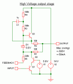
The circuit below could be a good starting point. ESL stators can be capacitor coupled or just left floating at +500V, assuming negative bias in the diaphragm.
Attachments
I realized after posting this that Ostripper likes to include multiple compensation schemes on his boards which he can switch between for comparison. That's probably what the cap mux is.
David.
intriguing, sounds feasible also. wouldnt this increase the loop area and be a bit counterproductive?
inquiring minds need to know what cap mux is
the semisouth jfets would surely be perfect candidates for the electrostatic drivers, with the r550 rated for 1700v
Last edited:
intriguing,sounds feasible also. wouldnt this increase the loop area and be a bit counterproductive?
inquiring minds need to know what cap mux is
the semisouth jfets would surely be perfect candidates for the electrostatic drivers, with the r550 rated for 1700v
Oh , linguistic semantics aside ... I know it is a multiplier. 😀 Bigun threw "MUX" at me and it "stuck".
Statement is a oxymoron but I will respond. Loop area won't increase (below 1) multiplier in/ out is 1.5CM (euroblock/ ksc3503/back to euroblock) decoupling goes to "clean ground" for separate voltage stage supply. Shrunk the multiplier down to 17 X 17mm. At the real estate required for a 1000uf/100v cap , 15K of emulated capacitance (100u X 150/3503-Hfe) is obtained along with 10db+ of PSRR .... not too counter productive. Less so than $100 cables or silver wire. 😱 PS= total cost , about $3.75 per amp (2 mults. for IPS/VAS stage). Way better deal than $200 "bybee power conditioners" (audio shampoo included).sounds feasible also. wouldnt this increase the loop area and be a bit counterproductive?
Yes , I have the full TMC/CMC/TPC - earth or rail blameless option on my "AX". TMC is the most "pleasing"(vas= lowest impedance).
OS
Attachments
Last edited:
nono, you misunderstood me (i think) that statement was in case you had included some sort of network of multiple compensation schemes, that can be switched in and out of the circuit (as was presented as an explanation above my post). i would think this wouldnt be so good for the feedback path increasing its physical size (loop area, literally). but i am by no means even close to an expert in this area, so it was a genuine question as its an area i'm trying to educate myself in
but its meaningless, because my first guesstimation that it was a cap multiplier was correct
but thankyou for the nice compact explanation of the cap mux cct above, it may come in handy for a battery operated cct i'm working on, that really doesnt need a regulator and board space is at a premium
but its meaningless, because my first guesstimation that it was a cap multiplier was correct
but thankyou for the nice compact explanation of the cap mux cct above, it may come in handy for a battery operated cct i'm working on, that really doesnt need a regulator and board space is at a premium
Last edited:
nono, you misunderstood me (i think) that statement was in case you had included some sort of network of multiple compensation schemes, that can be switched in and out of the circuit (as was presented as an explanation above my post). i would think this wouldnt be so good for the feedback path increasing its physical size (loop area, literally).
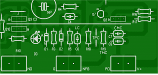
On that question, a pix will suffice (below) ... no long loops , just omitted components and a few jumpers will get any comp. scheme. 🙂
OS
Attachments
Aren't they scary expensive? A quick look in a local online catalog shows quite a few cheap but usable devices e.g:the semisouth jfets would surely be perfect candidates for the electrostatic drivers, with the r550 rated for 1700v
- MOSFET 1500V: $5
- BJT 1500V Vce: $2
- IGBT 1700V: $4
- ESBT 2200V: $6

How about that - I just learned something by mistake. I'd never heard of ESBTs before. 😱
Last edited:
^^^yeah, but not as much as r100 and not so much more than several other designed for audio mosfets. about 15 each matched from zhoufang in small numbers, so depending on the spread, if you need to match the above well, it may not end up all that much more.
but yes not cheap, but oh the sound!!
never heard of an esbt here either
thanks ostripper, interesting
but yes not cheap, but oh the sound!!
never heard of an esbt here either
thanks ostripper, interesting
Last edited:
Most ES speakers drive the two outside 'stators' in opposite phase from a balanced output. Most use a step-up xformer from a regular amp. Direct drive has advantages, but also disadvantages, the obvious one being the need for high output voltages. The quoted 500V is rather low; in my own ongoing design I shoot for +/-2kV RMS.
The moving diaphragm, sandwiched between the stators, is biased to a high-voltage to obtain a high static field strength to increase efficiency, typically to anything between 2 and 8kV DC. The diaphragm is made high impedance so that the speaker, really a balanced capacitor, operates at constant charge which linearizes the excursion vs drive voltage function.
jan didden
Hi Jan,
Thanks for the explanation.
Can you tell us a bit more about your ongoing design? Solid state? Maximum voltage?
Cheers,
Bob
It's a lot easier if you go for a class A design. This allows you to use only NPN (or N channel) devices in the output stage, and does away with the need for high-voltage driver circuitry.
The circuit below could be a good starting point. ESL stators can be capacitor coupled or just left floating at +500V, assuming negative bias in the diaphragm.
Hi Godfrey,
This looks like a great suggestion. Probably do-able with N-channel MOSFETs as well.
However, as with any class A design, what about power dissipation? Understood that the input impedance of the panel is high at low frequencies and primarily capacitive, but what is the capacitance and how much current is needed to drive the electrodes to the necessary very high slew rate at high frequencies? This might require a rather high class A bias current, and at these voltage levels dissipation will add up fast.
Cheers,
Bob
- Home
- Amplifiers
- Solid State
- Bob Cordell's Power amplifier book


