Scope traces from the VAS driver collector. All are 10 kHz square wave.
1 - 4 V out, 2 mV spikes
2 - 25 V out (safely below clipping), 50 mV spikes
3 - Hard clipping, spikes are 100 mV per division. I think the 0 V line is centered.
4 - Same but baseline moved up to show the bottom part of the spikes
Nice set of of pictures.
The spikes in the first two are because the comp network is being charged (and any parasitic capacitance connected to the node you are monitoring incl your probe capacitance). The main amplifier loop is driving this.
In the second two shots when the amplifier is clipping it is essentially running open loop while the clip is in progress. As the amplifier tries to recover, there is some overshoot within the loop and a bit of oscillation until the loop retains control.
One way to confirm this is to see if you have any rail sticking during hard clip - you should avoid that by employing a Baker clamp or one of the other techniques (see dadod and Ostripper for example).
Good advice from other posters on cascode oscillation and base stoppers - I’ve had issues in the small signal section on cascode with oscillation at c 180 MHz. In VAS stages it’s usually 10 or 20 x lower in frequency.
For some designers and some circuit applications, there may be additional factors to consider when choosing between the two.
_
Yes, the quasi sat of the 3503 starting at about 2.5V, versus that of the other device starting at below 1V, may be the price paid for the much lower capacitance of the 3503. We always have to pick our poison, but I would tend to sacrifice some quasi sat headroom to retain the other outstanding characteristics of the 3503.
Cheers,
Bob
The 1k value should be left alone.
The breadboard circuit did not include the output transistors doing so changes the rules of the game since these are slower than the driver transistors and also the load on the VAS collector transistor is increased reducing the loop gain.
You just have to accept in terms of your ceiling frequency that this is going to be lower and if you shoot to exceed this the EF2 stage will fall off the pace.
Apart from your EF2 output stage loading on your VAS transistor you have covered a number of bases for your compensation - TMC, Miller, and lag (your zobel).
The dominant pole has to be 10 times more effective in reducing frequency response than any other. You don't want to create rival poles to upset the balance of power.
You have your primary TMC network which should be sufficient if executed with the right value capacitors. Alternatively you could also try a single Miller capacitor.
In any case your capacitors should be NP0 dielectric types. Looking at the photo of your board I have doubts about this. As to values you will have to do this hands on by old fashioned trial and error.
If you are intent on TMC rather than Miller compensation the shorter route could be to start with a high value like 220 pF and see where this leads.
I largely agree. Get the design right with simple Miller compensation with a ULGF of 1 MHz or less first - then introduce TMC if you want. TMC is in no way for the less experienced. My approach to TMC is not the only way to do it, but I urge you to read carefully my chapter on TPC and TMC before proceeding with a TMC design.
The simplest TMC is to start with two caps in series, each twice the value of the MIller capacitor that gave really well-behaved performance. Then, gradually introduce lower and lower values of resistance from the center tap of those capacitors to the output node where the output emitter resistors meet. This approach is not optimum nor foolproof, but can be a starting point. Don't get greedy and overdo it. If you can't SPICE your TMC design, don't use TMC.
Cheers,
Bob
Hi All.
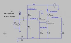
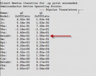
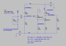
Just wondering if somebody can explain to me how the value of 200K was caculated for the input impedance to the Darlington VAS shown at the bottom of page 68 of bob 2nd edition.
I've attached some photos to help.
I thought that the input impedance was caculated from (22+2.6) x 100 (Q9) x 100 (Q8) Which totals 246K.
I understand that some of that will be lost because of R9 which has 0.5mA running through it, but I don't know how to calculate Bob's answer of 200K.
Can someone please help me understand how to calculate this.
Thanks.View attachment 809185
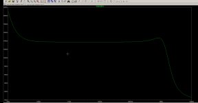
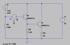
Tried to make a basic model of it in Ltspice
No luck 🙁
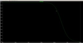
Yes, you have successfully simulated the input impedance of C1 feeding the R2/R3 potential divider (run the sim again with base of Q2 disconnected and you should get pretty much the same result, up to 200 kHz).
Then reconnect the base and run the simulation again, but this time plot (the voltage at Q2 base)/(Q2 base current). What do you see then?
Second book compared to first >?
Would anyone be willing to share feedback on the 2nd book relative to Bob's first book on Power Amplifiers? I own the first book (which is an invaluable source of information for amp designers) and am wondering if I need to sell it second hand and pick up the latest copy.
Is there a significant amount of new information, particularly regarding class A/B amplifiers (not class D, etc)? Thanks, Mike
In the emitter follower the input sees beta times impedance seen by the emitter - as the base voltage follows the emitter voltage (to 1st order), and the current ratio is beta.
So for instance an emitter loaded with 1k resistor and transistor with gain of 50 will look like 50 x 1k = 50k at the base. You can imagine a 20µA signal at the base becoming 1mA signal at the emitter due to the current gain. The 1k emitter resistor will make that 1V at the emitter, and thus at the base. All a.c. rms values.
So for instance an emitter loaded with 1k resistor and transistor with gain of 50 will look like 50 x 1k = 50k at the base. You can imagine a 20µA signal at the base becoming 1mA signal at the emitter due to the current gain. The 1k emitter resistor will make that 1V at the emitter, and thus at the base. All a.c. rms values.
Would anyone be willing to share feedback on the 2nd book relative to Bob's first book on Power Amplifiers? I own the first book (which is an invaluable source of information for amp designers) and am wondering if I need to sell it second hand and pick up the latest copy.
Is there a significant amount of new information, particularly regarding class A/B amplifiers (not class D, etc)? Thanks, Mike
For me, the major change was the addition of chapter 4, Building an Amplifier, where the evolution in chapter 3 is expanded to include the details for a complete amplifier. I'm sure others will note other changes and additions.
Tried to make a basic model of it in Ltspice
No luck 🙁
Well, in this case, your Zin is dominated by the R3 resistor value.
Zin will be equal something like this:
Zin = ( β7 + 1 ) * ( R8||( (β7 + 1)*(re7 + R9)) + re6)
So if we ignore re we have:
Zin = 101 * (2.2kΩ||(101*22Ω) ≈ 110kΩ
And the simulation result is closed to 120kΩ.
Open the sim file and plot V(N003,N002)/I(V2)
Attachments
Last edited:
Bob probably just calculated (Final_R_Emitter * Beta2 * Beta1) = 220K = "on the order of 200K"
Notice that this calculation becomes more and more accurate, as Beta becomes smaller and smaller.
I.e. the effect of the 2200 ohm resistor is less and less, when Beta is smaller and smaller.
Notice that this calculation becomes more and more accurate, as Beta becomes smaller and smaller.
I.e. the effect of the 2200 ohm resistor is less and less, when Beta is smaller and smaller.
Wow, a big thank you to HarryDymond, Mark Tillotson, jony. 
I really appreciate the input and the time taken by you guys to help me out.
Thank you jony for providing the math its a great help as I am a numbers man.
Zin = ( β7 + 1 ) * ( R8||( (β7 + 1)*(re7 + R9)) + re6)
I re-ran the results and yes I get approx 130K as Jony has shown.
The math if I have done it right comes out to 173K
I have also have attach my files if someone else wishes to play with this too.
So are we missing something or did Bob just round this to 200K for simplification?
I really appreciate the input and the time taken by you guys to help me out.
Thank you jony
for providing the math its a great help as I am a numbers man.Zin = ( β7 + 1 ) * ( R8||( (β7 + 1)*(re7 + R9)) + re6)
I re-ran the results and yes I get approx 130K as Jony has shown.
The math if I have done it right comes out to 173K
I have also have attach my files if someone else wishes to play with this too.
So are we missing something or did Bob just round this to 200K for simplification?
As Mark said, Bob probably just calculated (Final_R_Emitter * Beta2 * Beta1) = 220K = "on the order of 200K"
Attachments
Last edited:
Wow, a big thank you to HarryDymond, Mark Tillotson, jony.
No problem, you're welcome 🙂
The math if I have done it right comes out to 173K
So are we missing something or did Bob just round this to 200K for simplification?
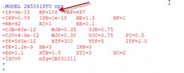
re ≈ 25/Ic, with Ic in milliamps, so re2 should be about 2.5 ohms in your calculation. I believe you'll then get an answer closer to the sim.
Note that the text in the book says the input impedance of the double EF is "the order of 200k". This is not the same as "200k", it's more like "approx. 200k".
It looks like you mixed the re1 with re2.Thank you jony
Zin = ( β6 + 1 ) * ( R8||( (β7 + 1)*(re7 + R9)) + re6)
I re-ran the results and yes I get approx 130K as Jony has shown.
The math if I have done it right comes out to 173K
re1 ≈ 26mV/10mA ≈ 2.6Ω
re2 ≈ 26mV/436µA ≈ 60Ω
Zin = ( β2 + 1 ) * ( R7||( (β1 + 1)*(re1 + R5)) + re2)
Zin = (101) * ( 2.2kΩ||( (101)*(2.6Ω + 22Ω)) + 60Ω) ≈ 124kΩ
Last edited:
Wow, a big thank you to HarryDymond, Mark Tillotson, jony.
I really appreciate the input and the time taken by you guys to help me out.
Thank you jony
Zin = ( β7 + 1 ) * ( R8||( (β7 + 1)*(re7 + R9)) + re6)
I re-ran the results and yes I get approx 130K as Jony has shown.
The math if I have done it right comes out to 173K
I have also have attach my files if someone else wishes to play with this too.
So are we missing something or did Bob just round this to 200K for simplification?
I think I just did it the simple way and rounded it, as Mark described above. The key words are "on the order of". Keep in mind that for beta ranges of 2:1 in each of the devices, the impedance number can have a range on the order of 4:1. I always get a laugh when I see in a manufacturer's SPICE model something like VA = 105.273. Give me a break 🙂.
Remember, good designs have minimal dependence on transistor current gain unless that current gain is quite small. Moreover, any design that depends on beta being SMALLER than some number is likely asking for trouble.
The SWAG is a highly valuable engineering tool when used properly.
Cheers,
Bob
Slightly off topic, but how much power do we really need? Here are some numbers to think about.
In December, I attended 3 days of musical performances at the Midwest Clinic at McCormick Place in Chicago. This conference features mostly high school and middle school orchestras, bands, and chamber groups along with a few military bands and community groups. Other than the one jazz room, there is no electronic amplification. I was usually seated around row 10 near the center aisle and took some rough measurements using a phone app (Decibel X). Loud passages were typically around 85 dB with peaks to 95 dB and a few slightly higher. A kettledrum explosion hit 102 dB.
What does this mean for a home system?
The well built, highly regarded, relatively inefficient, AR3a speaker has a sensitivity of 87 dB at 1 watt at 1 meter in an anechoic chamber. A home listening room will have reflections and a second speaker will add 3 dB. So, it appears that 1 watt per channel would get us to 90 dB. This would indicate that only 10 watts per channel would get us to 100 dB and 20 watts would cover the kettledrum blast. This is at a sound level equivalent to that of the live performance in the home listening room.
.....
In the second two shots when the amplifier is clipping it is essentially running open loop while the clip is in progress. As the amplifier tries to recover, there is some overshoot within the loop and a bit of oscillation until the loop retains control.
One way to confirm this is to see if you have any rail sticking during hard clip - you should avoid that by employing a Baker clamp or one of the other techniques (see dadod and Ostripper for example).
.....
There is some rail sticking at clipping and on a more sophisticated project I'd look at the Klever Klipper or similar. In this receiver restoration, I'm out of space and it is unlikely to ever be driven that hard anyway.
Slightly off topic, but how much power do we really need? Here are some numbers to think about.
In December, I attended 3 days of musical performances at the Midwest Clinic at McCormick Place in Chicago. This conference features mostly high school and middle school orchestras, bands, and chamber groups along with a few military bands and community groups. Other than the one jazz room, there is no electronic amplification. I was usually seated around row 10 near the center aisle and took some rough measurements using a phone app (Decibel X). Loud passages were typically around 85 dB with peaks to 95 dB and a few slightly higher. A kettledrum explosion hit 102 dB.
What does this mean for a home system?
The well built, highly regarded, relatively inefficient, AR3a speaker has a sensitivity of 87 dB at 1 watt at 1 meter in an anechoic chamber. A home listening room will have reflections and a second speaker will add 3 dB. So, it appears that 1 watt per channel would get us to 90 dB. This would indicate that only 10 watts per channel would get us to 100 dB and 20 watts would cover the kettledrum blast. This is at a sound level equivalent to that of the live performance in the home listening room.
Hi Fred,
Peter Smith and I gave a series of workshops at RMAF 2006 and Home Entertainment 2007 (HE2007), one of which was a real-time demonstration of peak power requirements encountered in well-recorded music (i.e., little or no compression). A specialized meter was built where average power calibrated for 8 ohms was displayed in one digital meter and the peak power was displayed in the other meter. For a sine wave, both meters read identically. You can go to my website and click on the HE2007 tab to read the full show report that includes a detailed description of the peak power demonstration.
CordellAudio.com - Home Entertainment Show 2007
Speakers with estimated sensitivity of 89 dB SPL/1Meter were used and were driven by a 250 wpc amplifier. The demo was given in a standard hotel exhibit room. A cut from the Rickie Lee Jones "Flying Cowboys" CD was played. This album was mastered with little compression and had the most dynamic range of any CD I have encountered and measured. I have been told that later versions of this CD were re-mastered with less dynamic range.
At realistic, but comfortable, listening levels the average power was in the 1-2 watt range. Some peaks hit 250 watts. These were mainly from aggressive percussive "thwacks" on a snare drum from the "Ghetto of My Mind" cut. Listening distance was about 10 feet. While few CD recordings have this much dynamic range, this is a sobering reminder of the amount of power that can be required. I encourage you to visit the web site and read the full report. There is also a description of the peak/average meter under the Audio Instrumentation tab at cordellaudio.com.
Cheers,
Bob
Was that actual power or voltage converted to power? I drove a vendor nuts building a digital power meter for audio that actually measured the instantaneous power with a fast attack and slow decay (otherwise the digits were a complete blur). It was on the Monster power amp with Richard's amp circuit in it.
Thanks for the correction.It looks like you mixed the re1 with re2.
- Home
- Amplifiers
- Solid State
- Bob Cordell's Power amplifier book