By the way you want the third "helper" transistor in the 3-transistor current mirror, to exactly match the emitter follower in the "Darlington VAS". So you want to run them at the exact same current. So you want them to have the exact same resistance in the emitter leg. You can see that Dave Fullegar did this very thing in 1969 when he designed the famous uA741 opamp, schematic below. This was four years before the SPICE simulator was created.
That adds a whole new slew of Goldilocks zone multi-convergence constraints, mostly having to do with the goal of super-low DC offset more than anything else. I would rather handle offset in other ways, get better performance and use less parts. It sounds really nice but you always have to consider your design goals and grand schemes like this have a tendency to box you into a specific topology that may be painful to deconstruct later.
except that you don't want the actual Darlington connection of the VAS buffer Q collector - both 'helpers' collectors should go to the same V
the mirror and helper Qs can all operate at low V and could be from a monolithic matched Quad if you think hfe matching as well as vbe is good
the mirror and helper Qs can all operate at low V and could be from a monolithic matched Quad if you think hfe matching as well as vbe is good
Thanks Mark. I appreciate your insightful response.I recommend choosing the emitter degeneration resistors in a current mirror, large enough that the voltage dropped across them is at least 20 times bigger than the worst case delta-VBE (a/k/a "VBE mismatch") you might ever get between the two transistors in the current mirror. So, for example, if you expect you might get a 10 millivolt difference in VBE, drop at least 200 millivolts across the emitter degeneration resistors.
By the way you want the third "helper" transistor in the 3-transistor current mirror, to exactly match the emitter follower in the "Darlington VAS". So you want to run them at the exact same current. So you want them to have the exact same resistance in the emitter leg. You can see that Dave Fullegar did this very thing in 1969 when he designed the famous uA741 opamp, schematic below. This was four years before the SPICE simulator was created.
_
300mV is a good figure for current mirror degeneration for noise, you don't get much better by going higher.
Rbias/Rdegen should be >> Hfe of the current mirror transistors, as a basic rule of thumb, so that the benefit of the current mirror Hfe isn't lost due to the bias resistor. In this case, 40kRbias/100Rdegen=400 whereas Hfe is 100. Notice that you can't increase Rdegen in this case. If we increase degeneration to 300mV by increasing Rdegen to 300, then 40kRbias/300Rdegen=133.
Note that an Hfe of 100 is pretty low considering what we usually use for current mirrors. The situation gets worse when you use for instance the BC550C with 500Hfe.
So this kind of current mirror has a lot of damned if you do, damned if you don't type of stuff going on. That's why I never use it, in practice it's actually terrible in terms of linearity.
I have to disagree. I use the 3-transistor current mirror with the EF helper all of the time, and its use in BJT linear integrated circuits is commonplace. I have never seen a linearity problem with its current transfer with any reasonable value for the helper pull-down resistor. For a typical IPS mirror with 1mA in and out, I usually use 220 ohms for degeneration (about 9X re' of the mirror transistors).
In such an application, I usually use a pull-down of 2.2k or 4.7k, pulling about 400 or 200 uA, respectively. This may seem like a lot, but I like to run the helper at the same current as the EF in the subsequent 2T VAS, equalizing the collector voltages of the two mirror transistors. This allows me to use anti-parallel diodes across the IPS collectors to help control clipping behavior. The EF in the 2T VAS must have sufficient pull-down current so as to remain greater than the current though the Ccb of the VAS transistor under maximum slew rate conditions.
Running the mirror helper at 200uA or more keeps the ft of the helper up. This has its positive and negative consequences. It keeps currents under good control and does not allow the use of a slow helper to degrade mirror speed. However, it can reduce phase margin in the tight mirror feedback loop thus formed. There can also be some interaction with the output of the mirror looking into the quasi-virtual-ground formed at the 2T VAS input by the Miller compensation. For this reason, I will often put about 470pF from base to emitter of the helper transistor to slow that loop down a bit. The 470pF value tends to tame the mirror at HF without compromising its speed.
The 3T mirror also has the strong advantage of giving the input transistor of the mirror more than 0V Vcb headroom by one Vbe. This keeps that transistor further away from quasi-saturation and makes it behave much more like the other mirror transistor. This can actually reduce distortion.
In principle, the pull-down bias of the helper detracts a bit from the DC accuracy of the mirror, due to the base current of the helper. But we really don't care much about the DC accuracy of the mirror in this application (as long as it does not create significant imbalance in the LTP transistors). It's not much current anyway, and the accuracy is still far better than that of the 2T mirror, where the base current of both mirror transistors creates error.
Note that the current mirror gives us common mode rejection to changes in the sum of the currents in the two LTP transistors. For this reason, we like to have good AC current mirror accuracy. Once again, that accuracy is much greater with the 3T current mirror than with the 2T current mirror.
If we wanted to, we could largely AC bootstrap the pull-down resistor by using 2 pull-down resistors, each one connected to the emitter of a mirror transistor instead of a single pull-down resistor to the negative rail.
Cheers,
Bob
Fair enough.
I've never had stringent DC offset requirements and whenever I found a benefit to be had in an advanced current mirror, I found other parts of the circuit were partly to blame and addressing them had more benefit than using a 3-transistor current mirror.
Ultimately if it improves your circuit you should use it, there is no substitute for doing your own investigation.
there may be bigger fish to fry...
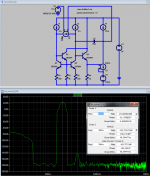
mirror embedded in loop with ideal sources, not much to worry over with -165 dB @20k of these 4 Q
mirror embedded in loop with ideal sources, not much to worry over with -165 dB @20k of these 4 Q
Attachments
Last edited:
...worst case delta-VBE (a/k/a "VBE mismatch")...a 10 millivolt difference in VBE, drop at least 200 millivolts...
This completely misses the noise implications.
Even if the transistors were perfectly matched it would still be advisable to drop >> 26mV.
Much past 260 mV or so the noise contribution from the resistors is so low that further reduction is barely useful in an audio amp.
It is sometimes useful to drop more than 260 mV, not for noise reasons but to balance the potential at the VAS and current mirror.
This makes it possible to eliminate the helper transistor and still have DC balance.
This is nice but usually not too important.
For certain symmetrical circuits it is more important (see "Slone amplifier problems")
Best wishes
David
Last edited:
...
Even if the transistors were perfectly matched it would still be advisable to drop >> 26mV.
Much past 260 mV or so the noise contribution from the resistors is so low that further reduction is barely useful in an audio amp.
...
My 2StageEF variants use ~ 600mv current mirror degeneration for lowest noise and DC balance. Have a look here for a effect I got due to too high degeneration: 2stageEF high performance class AB power amp / 200W8R / 400W4R
(Current mirror current per leg: 3 - 3.5mA)
BR, Toni
Last edited:
Even if the transistors were perfectly matched it would still be advisable to drop >> 26mV.
I suppose so; but the discrete transistors I buy in real life, seem to always have at least 2-4 millivolts of delta-VBE when I measure a small population (50 parts), presumably more across a big population. Even the input transistors of an opamp, built right next to each other on the same piece of silicon, routinely have 5mV of delta-VBE. Thus a lower bound of at least ~ 100 millivolts across the degeneration resistors, seems prudent.
Bob Cordell's idea in post #8784, to set Rdegen = (9 * VT / Icollector), puts 234 mV across the degeneration resistors. Enough to deal with ~ 12 mV of delta-VBE. Nice.
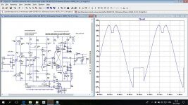
R20+R21 are very low. I used 47k or similar.I noticed strange clipping in my GaiWire preamp where this kind of 3T current mirrors where used. When I switched to ordinary 2T current mirror problem was solved.
R20+R21 are very low. I used 47k or similar.
No difference at all, I went up to 100k with the same result.
I noticed strange clipping in my GaiWire preamp where this kind of 3T current mirrors where used. When I switched to ordinary 2T current mirror problem was solved.
The current mirror helper EF is over-driving the VAS transistor into saturation and pushing enough current base to emitter to lift the emitter off of the rail. The 2T current mirror cannot source enough current into the VAS base to do this. The VAS should have a current-limiter transistor on it.
Cheers,
Bob
Noise
Hopefully Bob will include chapters about pre amps and low noise designs in his new book. In that case I think that a RE voltage drop of a few 100 mV in CCS and CM isn't even close to what is needed
In a power amp it might be ok if you only look at the THD and not the THD+N.
All the best
Reodor
Hopefully Bob will include chapters about pre amps and low noise designs in his new book. In that case I think that a RE voltage drop of a few 100 mV in CCS and CM isn't even close to what is needed
In a power amp it might be ok if you only look at the THD and not the THD+N.
All the best
Reodor
Hopefully Bob will include chapters about pre amps and low noise designs in his new book. In that case I think that a RE voltage drop of a few 100 mV in CCS and CM isn't even close to what is needed
In a power amp it might be ok if you only look at the THD and not the THD+N.
All the best
Reodor
Hi Reodor,
I think to cover preamps would take a whole 'nother book. While I won't have a chapter on preamps, I do have a whole new chapter on noise, and low-noise design. Many are in fact interested in low noise in power amplifiers. One thing to bear in mind is that a power amplifier comes AFTER the volume control, so whatever noise it makes is there all the time. Couple that with the possibility that one will be using high-efficiency speakers, and you begin to want noise performance that is perhaps on a par with preamplifier line-level circuits. A power amplifier with 5 nV/rt Hz input-referred noise is quite good.
BTW, I did do some writing on low-noise circuits in the VinylTrak preamp article I wrote sometime ago in Linear Audio.
Cheers,
Bob
First thing I would try is collector resistors on Q21 and Q22. When it overdrives the CM helper transistors can pull an indefinite amount of current out of the VAS collectors through the base. This occurs as phase inversion.
Hi All. Its been great reading everybody's responses to my current mirror questions I am planing on test some of the response infomation on the weekend. I was just wondering if anybody had a Spice file that allows me to just simulate a single ended Input stage with a Dc ails, current source, differential pair, current mirror, negative feedback etc.. and then whatever other components that I need to allow me to simulate the circuit using Lt Spice.
First thing I would try is collector resistors on Q21 and Q22. When it overdrives the CM helper transistors can pull an indefinite amount of current out of the VAS collectors through the base. This occurs as phase inversion.
There is no VAS, just current conveyor. I think that with current conveyor the helper transistor is doing more harm than help. And this happened only in feedback mode, in non feedback it behaves OK.
First thing I would try is collector resistors on Q21 and Q22. When it overdrives the CM helper transistors can pull an indefinite amount of current out of the VAS collectors through the base. This occurs as phase inversion.
This sort of thing is one of the reasons I wanted to put anti-polarity clamp diodes across the IPS collectors, so as to limit the voltage swing in clipping to no more than +/- one Vbe about the nominal voltage. One concern in the 2T VAS is over-current in the EF transistor when it tries to drive the emitter of the saturated VAS transistor through its base. There can even be a safe area concern for that EF transistor. With the positive swing out of the mirror limited to no more than 1Vbe above nominal, the amount of this over-current is easier to control. In my design, I place a 50-ohm resistor between the emitter of the emitter follower and the base of the VAS transistor. This, in combination with the typical 22-ohm VAS transistor emitter degeneration helps limit the current in the EF transistor during clipping.
Cheers,
Bob
Bob, what about using jfet as a helper transistor in current mirror? Perhaps it takes a LED or something similar in series with source to get proper voltages. It would certainly improve the speed and linearity, plus the value of the third (non degenerative) resistor would be much less critical.
- Home
- Amplifiers
- Solid State
- Bob Cordell's Power amplifier book