Hi Damir,
I have not yet had a chance to look at it in detail, but a quick look suggests that your OITPC scheme and your simulation results show some promise. Thanks for sharing it!
Cheers,
Bob
Thank you Bob for your time. This is not only simulation, I actually built few working amps, CFA and VFA, with very good result.
Best wishes,
Damir
dadod
I can confirm that OITPC works very very well. So far I have build only one amplifier with this kind of compensation, amplifier is rock stable, on the square wave tests with capactive load (8R +0,47uF) there is absolutely no visible change/overshoot at all. For sure it is good.
The only thing in my case is that I was not fully satisfied with the mid and top octave, sound was kind of flat - but this is probably the project issue itself.
Next time I will try to prepare some more ''classic'' amplifier with OITPC.
Regards
Attachments

dadod
I can confirm that OITPC works very very well. So far I have build only one amplifier with this kind of compensation, amplifier is rock stable, on the square wave tests with capactive load (8R +0,47uF) there is absolutely no visible change/overshoot at all. For sure it is good.
The only thing in my case is that I was not fully satisfied with the mid and top octave, sound was kind of flat - but this is probably the project issue itself.
Next time I will try to prepare some more ''classic'' amplifier with OITPC.
Regards
Borys if you mean the attached schematic, this is TMC not OITPC I described in my OITPC thread. www.diyaudio.com/forums/solid-state/317335-oitpc-output-inclusive-tpc-tmc.html
BR Damir
dadod
Thank a lot, I will read it again with pleasure.
Regards
You are welcome. I follow your designs with great interest.
BR Damir
Yes, it is going very well. The final manuscript will be complete in April. The second edition should be out before the end of the year. It will have 36 chapters and be about 750 pages long.
Cheers,
Bob
Cool, five new chapter (150 more pages) sound very good.
Have you rewritten all the chapters? Or you just "fix" the "errors" in the old one and wrote the new chapters about the new subjects?
Cool, five new chapter (150 more pages) sound very good.
Have you rewritten all the chapters? Or you just "fix" the "errors" in the old one and wrote the new chapters about the new subjects?
All of the existing chapters have been at least revised and updated and corrected, but some more than others. I have received a great many comments, corrections and suggestions from my friends here over the years, and for that I am very grateful.
Cheers,
Bob
Current Mirror Question
Hi All,
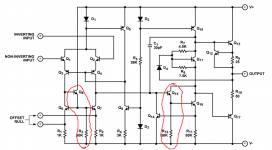
I was watching a Burning amp 2016 youtube clip were Bob was talking. (great video by the way YouTube ) I noticed that on one of Bob's circuit diagrams he show a extra resistor connected from the base to the negative rail on his current mirror shown a "1" in my attached diagram.
Could someone please explain to me the purpose of this resistor. I was thinking that it may possibly help drain the base current from the two transistors when you want them to turn off, but I am not sure.
The other question that I have is regarding the selection to the degeneration resistors for the current mirror. Is there a rule of thumb for this or a way to calculate the best value for them. Shown a "2" in my attached diagram.
Hi All,
I was watching a Burning amp 2016 youtube clip were Bob was talking. (great video by the way YouTube ) I noticed that on one of Bob's circuit diagrams he show a extra resistor connected from the base to the negative rail on his current mirror shown a "1" in my attached diagram.
Could someone please explain to me the purpose of this resistor. I was thinking that it may possibly help drain the base current from the two transistors when you want them to turn off, but I am not sure.
The other question that I have is regarding the selection to the degeneration resistors for the current mirror. Is there a rule of thumb for this or a way to calculate the best value for them. Shown a "2" in my attached diagram.
Attachments

It increases the current through the top transistor, which increases it's Ft and keeps it from turning on and off during operation. With only the base currents to bias it it will be very slow, and this can cause phase problems in the feedback loop. It also has to drive the mirror's base capacitances, which allow the base currents to be negative at times. An NPN transistor cannot supply negative current, so it needs extra bias to absorb the capacitive currents.
This resistor introduces some nonlinearity due to converting the nonlinear Vbe of the current mirror, so it can be a damned if you do, damned if you don't sort of thing.
This resistor introduces some nonlinearity due to converting the nonlinear Vbe of the current mirror, so it can be a damned if you do, damned if you don't sort of thing.
It increases the current through the top transistor, which increases it's Ft and keeps it from turning on and off during operation. With only the base currents to bias it it will be very slow, and this can cause phase problems in the feedback loop. It also has to drive the mirror's base capacitances, which allow the base currents to be negative at times. An NPN transistor cannot supply negative current, so it needs extra bias to absorb the capacitive currents.
This resistor introduces some nonlinearity due to converting the nonlinear Vbe of the current mirror, so it can be a damned if you do, damned if you don't sort of thing.
Thank you for the great detailed explanation really appreciate your time.
I also found that if I lower resistor 1 to much the current becomes to high and actually pulls out base current which affects the accuracy of the current mirror.
Do you have any advice on the selection of the degeneration resistors?
Last edited:
Do you have any advice...
Keantoken has left the forum for the moment, so if I may comment.
It's easiest to make the recommendation in terms of the potential across the resistors.
For reduced noise it should be >> 26 mV, say 260 mV .
Best wishes
David
That may seem counter intuitive but there's quite a bit of discussion in this forum.
One of my first posts here was about exactly this problem, I received some excellent replies.
Noise of LTP input? Help!
Last edited:
300mV is a good figure for current mirror degeneration for noise, you don't get much better by going higher.
Rbias/Rdegen should be >> Hfe of the current mirror transistors, as a basic rule of thumb, so that the benefit of the current mirror Hfe isn't lost due to the bias resistor. In this case, 40kRbias/100Rdegen=400 whereas Hfe is 100. Notice that you can't increase Rdegen in this case. If we increase degeneration to 300mV by increasing Rdegen to 300, then 40kRbias/300Rdegen=133.
Note that an Hfe of 100 is pretty low considering what we usually use for current mirrors. The situation gets worse when you use for instance the BC550C with 500Hfe.
So this kind of current mirror has a lot of damned if you do, damned if you don't type of stuff going on. That's why I never use it, in practice it's actually terrible in terms of linearity.
Wow. Thank you so much. Really happy with your adviceKeantoken has left the forum for the moment, so if I may comment.
It's easiest to make the recommendation in terms of the potential across the resistors.
For reduced noise it should be >> 26 mV, say 260 mV .
Best wishes
David
That may seem counter intuitive but there's quite a bit of discussion in this forum.
One of my first posts here was about exactly this problem, I received some excellent replies.
Noise of LTP input? Help!
Thank you as well you help and advice really help me understand this much better.300mV is a good figure for current mirror degeneration for noise, you don't get much better by going higher.
Rbias/Rdegen should be >> Hfe of the current mirror transistors, as a basic rule of thumb, so that the benefit of the current mirror Hfe isn't lost due to the bias resistor at AC. In this case, 40kRbias/100Rdegen=400 whereas Hfe is 100. Notice that you can't increase Rdegen in this case. If we increase degeneration to 300mV by increasing Rdegen to 300, then 40kRbias/300Rdegen=133.
Note that an Hfe of 100 is pretty low considering what we usually use for current mirrors. The situation gets worse when you use for instance the BC550C with 500Hfe.
So this kind of current mirror has a lot of damned if you do, damned if you don't type of stuff going on. That's why I never use it, in practice it's actually terrible in terms of linearity.
What type of circuit do suggest that I use for a current mirror them. Can you please post and example.300mV is a good figure for current mirror degeneration for noise, you don't get much better by going higher.
Rbias/Rdegen should be >> Hfe of the current mirror transistors, as a basic rule of thumb, so that the benefit of the current mirror Hfe isn't lost due to the bias resistor. In this case, 40kRbias/100Rdegen=400 whereas Hfe is 100. Notice that you can't increase Rdegen in this case. If we increase degeneration to 300mV by increasing Rdegen to 300, then 40kRbias/300Rdegen=133.
Note that an Hfe of 100 is pretty low considering what we usually use for current mirrors. The situation gets worse when you use for instance the BC550C with 500Hfe.
So this kind of current mirror has a lot of damned if you do, damned if you don't type of stuff going on. That's why I never use it, in practice it's actually terrible in terms of linearity.
I shouldn't say it's terrible, since it can work well, but I've never seen the need to fight with it rather than use another kind of current mirror.
I recommend choosing the emitter degeneration resistors in a current mirror, large enough that the voltage dropped across them is at least 20 times bigger than the worst case delta-VBE (a/k/a "VBE mismatch") you might ever get between the two transistors in the current mirror. So, for example, if you expect you might get a 10 millivolt difference in VBE, drop at least 200 millivolts across the emitter degeneration resistors.
By the way you want the third "helper" transistor in the 3-transistor current mirror, to exactly match the emitter follower in the "Darlington VAS". So you want to run them at the exact same current. So you want them to have the exact same resistance in the emitter leg. You can see that Dave Fullegar did this very thing in 1969 when he designed the famous uA741 opamp, schematic below. This was four years before the SPICE simulator was created.
_
Attachments
Im not sure how the 40k is used as Rbias in your calculation as the current is not flowing through it and into the base. Can we use Ib/Ie ?I shouldn't say it's terrible, since it can work well, but I've never seen the need to fight with it rather than use another kind of current mirror.
The voltage across the degeneration also appears across the 40k resistor, hence for every 1mA through the degeneration, there will be 100mV across the 40k resistor. 100mV/40k=2.5uA per 1mA Ie. So it acts like Hfe, it isn't a physical Hfe. It is a parasitic effect of the 40k resistor.
- Home
- Amplifiers
- Solid State
- Bob Cordell's Power amplifier book