X and Y caps are rated for international safety standard purposes (UL, VDE CSA etc) more than best filtering capability though the actual function of these caps and related inductor on an SMPS is to reduce the inevitable switching and RF noise that is conducted back down into the mains supply so unlikley to have an effect on the SMPS outputs, though a few years in analogue and SMPS design confirms that life is never simple so never say never. AdrianS
...but also keep in mind that the unwanted hash from the SMPS may be able to escape out the other way, down the mains lead. This can potentially affect adjacent equipment.
Bob Cordell said:
You may wish to build them both and simulate as well, as mentioned above. However, I think in fairness you also need to convince yourself that either of these is better than a properly-applied LM337.
Cheers,
Bob
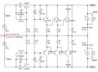
I have another version of super shunt PSU.
Zout = 0.9ohm and PSRR=83dB, from DC to 460khz then drop with 6dB/octave
Very stable in simulator ...
There is any other simple method to do it with few components?
Attachments
Hi Roender,
why do you choose a fairly fast transistor for the CCS but a fairly slow transistor for the final shunt element?
If the last shunt element had higher gain, could the middle bc550 be omitted? or would this screw up all the good characteristics?
Is there a way to monitor the current in the shunt so that the CCS can be trimmed to =[output current+7mA]. I'm thinking about a ClassA amplifier load of 20 to 30mA with little variation with signal and would like to use a To92 (200mW+-100mW) shunt element passing just 5mA+-2.5mA.
AndrewT said:Hi Roender,
1. If the last shunt element had higher gain, could the middle bc550 be omitted? or would this screw up all the good characteristics?
2. Is there a way to monitor the current in the shunt so that the CCS can be trimmed to =[output current+7mA]. I'm thinking about a ClassA amplifier load of 20 to 30mA with little variation with signal and would like to use a To92 (200mW+-100mW) shunt element passing just 5mA+-2.5mA.
1. We need a very high impedance over zener ...
2. I don't think that you need to monitor/trim the ccs if the load is constant, only set the DC point for your needs
Can I interpret that to mean 4*10^6 current gain is required?roender said:1. We need a very high impedance over zener ...
but the ClassA amplifier is not constant current. Whether it's a single ended discrete opamp or a push pull discrete opamp or the front end of a power amp, they all vary their current demand with the signal. That's why I showed a typical +-2.5mA, although I reckon it can go to 32mA+-8mA in the Krell Clone front end (excluding drivers).roender said:2. I don't think that you need to monitor/trim the ccs if the load is constant, only set the DC point for your needs
I have built up PMA's version and I can see no way to measure the shunt current unless I add a monitoring resistor into the circuit. I can only calculate the shunt current by subtracting all the other currents from the CCS set current.
AndrewT said:
1. Can I interpret that to mean 4*10^6 current gain is required?
2. but the ClassA amplifier is not constant current. Whether it's a single ended discrete opamp or a push pull discrete opamp or the front end of a power amp...
1. Yes, as high as possible. You could replace small signal bjt's with a jfet ...
2. Only brute force can solve this problem. Make I CCS = 10xDeltaI.
roender said:
I have another version of super shunt PSU.
Zout = 0.9ohm and PSRR=83dB, from DC to 460khz then drop with 6dB/octave
Very stable in simulator ...
There is any other simple method to do it with few components?
I would think that if you were willing to go to a dc Zout of 2 ohms, you could further improve PSRR bandwidth by adding a 1 ohm series resistor at the end, followed by a 100 uF || 1 uF shunt capacitance to ground.
Cheers,
Bob
Hi all,
I am a little confused about this superreg preceding the gyrator. The numbers quoted for the Zout and the PSRR are worse than for a properly executed superreg alone.
For example, a reasonable superreg can easily go down to a few milliohms over the audio band. With the high gyrator output Z, the modulation of the output voltage by the load current is significant, and probably higher than any remaining reg noise anyway. A load variation of say 10mA over a 1ohm Zout is 10mV ripple, huge wrt any microvolt reg noise and ripple.
So, why should we built a good superreg and then throw away a lot of the goodies with a following gyrator?
Jan Didden
Hi Jan - The iterations that have been recommended though are using gyrators to knock noise off the raw supply before the Super-reg. This does offer some merit, since HF rejection of the typical LM317 is pretty dismal (my crude demo is here: http://www.acoustica.org.uk/t/3pin_reg_notes2.html). In contrast , the gyrator is basically a brute-force RC filter with an emitter-follower bolted-on to make the output impedance more reasonable.
I have reservations about the other way round for exactly the reasons you identify, though in the interest of an open mind I did try it. It's not for me.
I have reservations about the other way round for exactly the reasons you identify, though in the interest of an open mind I did try it. It's not for me.
janneman said:Hi all,
I am a little confused about this superreg preceding the gyrator. The numbers quoted for the Zout and the PSRR are worse than for a properly executed superreg alone.
For example, a reasonable superreg can easily go down to a few milliohms over the audio band. With the high gyrator output Z, the modulation of the output voltage by the load current is significant, and probably higher than any remaining reg noise anyway. A load variation of say 10mA over a 1ohm Zout is 10mV ripple, huge wrt any microvolt reg noise and ripple.
So, why should we built a good superreg and then throw away a lot of the goodies with a following gyrator?
Jan Didden
Hello Jan,
Apparently there was a great article by Sulzer I beleive in AA in the '80s about making a high current version of the superreg's or it's non-bootstrapped predecesor!. Never obtained a copy however. Voltage is not a problem in class A power amp reg designs. My question for you in the original design it tended to use low Pd devices T-092 but there GBP (ft) also tends to be quite high at even very low currents. Now if we take a 2SC3281 power bjt it's GBP [ft) is diabolical at low current levels!. <3 mhz ft and would almost certainly affect stability margins in the reg.
Remember you once saying using mosfets in this applicaton reduced performance by an order of magnitude (lack of gain) and hence the holy grail "Zout" but I am starting to disagree!
Mosfets have incredibly high GBP at all drain currents - assisting loop stability so could make a high current version stable whereas a array/ring emitter BJT type may not.
Kevin
Noise on Power Supplies
While on the topic of regulators for power supplies in audio, both IC regulators and super-regulators, here is a bit of a Devil's Advocate question.
It is certainly a good thing to have the lowest noise possible on the power supply lines, no one questions that. But at what point does further reduced noise cause improved sonics? And at what price?
If the noise is benign (and this is sometimes a big IF), why should we care if the noise on the power supply is low enough that it is not close to being a dominant factor in establishing the overall noise performance of the amplifier?
Suppose I have an amplifier that has achieved a very respectable 100 dB S/N with respect to 1 watt that has been made with simple LM317/337 regulators in the supply lines of the front end. Now lets suppose I replace the LM317/337s with discrete super regulators and I again measure the amplifier's noise performance and see no difference (the noise is probably dominated by that of the input stage, for example). Why should I hear any sonic improvement in this case due to reduced noise on the power supply rails?
There are typically three types of noise at the output of a power supply regulator. The first is electronic circuit noise from the regulator itself. This is fairly white to begin with and is uncorrelated with the signal.
The second is the remainder of power source noise that has not been rejected by PSRR of the regulator. This noise will largely consist of ripple and rectifier noise and perhaps some RFI. In any decent design, the magnitude of this noise should be small enough that its interaction will be linear with the amplifier circuit - in other words, it will be additive in the output and will not intermodulate with the audio signal to create new spectral components. This may be an important IF to watch out for, but any such interaction should be measureable on a spectrum analyzer under the right conditions.
The third is noise caused by the amplifier's own signal-dependent rail currents acting against the output impedance of the regulator. These are obviously correlated to the signal and may be able to cause harm if the resulting noise voltage on the rail is large enough. This presumably can be evaluated by spectrum analysis of what is on the regulated rails.
Finally, all of this would seem to depend on the PSRR vs frequency of the amplifier itself. From this perspective, one might question how the introduction of a super-regulator in place of an IC regulator improves the sonics of an amplifier that already has very good PSRR.
Finally, putting a super-regulator in an amplifier design that does not already have good inherent PSRR would seem to be a backwards set of priorities. Perhaps this scenario would come into play in minimalist designs that may tend to inherently have lass PSRR.
Just some controversial thoughts here. In all of this, of course, we must not leave out the possibility of the X-factor, where there are sonic effects that may not be completely understood based on what we think we know.
Cheers,
Bob
Controversial is my middle name.
If the PSRR of the amp degrades to -40db @ 100kHz on the negative line and the PSRR of the cheap/easy single chip regulator also degrades to a similar figure @ the same passband frequency, then that is a total attenuation of near 80db on the output.
In the meantime the circuitry of the amp has had to handle all that non-correlated noise while trying to amplify the wanted signal.
I suspect some interaction and that the products of this interaction could be above the -80db level.
Now take your -100db below max output noise figure.
That's not good enough. It's an OK figure but we can do a lot better.
I would try for -90dbW and maybe even set the target at -100dbW.
The noise at the output should then come out as just about inaudible using 100db/Wm speakers (provided there are no exaggerations at any particular freqencies/bands).
martin clark said:Hi Jan - The iterations that have been recommended though are using gyrators to knock noise off the raw supply before the Super-reg. This does offer some merit, since HF rejection of the typical LM317 is pretty dismal (my crude demo is here: http://www.acoustica.org.uk/t/3pin_reg_notes2.html). In contrast , the gyrator is basically a brute-force RC filter with an emitter-follower bolted-on to make the output impedance more reasonable.
I have reservations about the other way round for exactly the reasons you identify, though in the interest of an open mind I did try it. It's not for me.
Yes, doing some noise & ripple reduction BEFORE the reg certainly makes sense, but NOT the other way around! BTW, that 'gyrator' of course is NOT a gyrator, it's just an emitter follower as you noted. A gyrator is something else.
Jan Didden
Fanuc said:
Hello Jan,
Apparently there was a great article by Sulzer I beleive in AA in the '80s about making a high current version of the superreg's or it's non-bootstrapped predecesor!. Never obtained a copy however. Voltage is not a problem in class A power amp reg designs. My question for you in the original design it tended to use low Pd devices T-092 but there GBP (ft) also tends to be quite high at even very low currents. Now if we take a 2SC3281 power bjt it's GBP [ft) is diabolical at low current levels!. <3 mhz ft and would almost certainly affect stability margins in the reg.
Remember you once saying using mosfets in this applicaton reduced performance by an order of magnitude (lack of gain) and hence the holy grail "Zout" but I am starting to disagree!
Mosfets have incredibly high GBP at all drain currents - assisting loop stability so could make a high current version stable whereas a array/ring emitter BJT type may not.
Kevin
Hi Kevin,
There are several issues here mixing themselves up. Firstly, using a 2SC3281 for low current applications (100mA?) doesn't make sense for the reason you mentioned. BUT if you need a high current reg (say for a class A amp) that 2SC3281 does make sense and the low beta at low Ic issue goes away. In the 'superreg' a lot of people use those D44-types and they have good gain linearity at lower currents.
If you use the right BJT for a 'superreg', changing it out for a mosfet will most probably lead to lower loop gain and lower performance but I know I shouldn't make blanket statements here without knowing all the particular circuit details. Another issue with mosfets is the higher drive voltage required although the low-Vgs types may be better here.
Jan Didden
AndrewT said:Controversial is my middle name.
If the PSRR of the amp degrades to -40db @ 100kHz on the negative line and the PSRR of the cheap/easy single chip regulator also degrades to a similar figure @ the same passband frequency, then that is a total attenuation of near 80db on the output.
In the meantime the circuitry of the amp has had to handle all that non-correlated noise while trying to amplify the wanted signal.
I suspect some interaction and that the products of this interaction could be above the -80db level.
Now take your -100db below max output noise figure.
That's not good enough. It's an OK figure but we can do a lot better.
I would try for -90dbW and maybe even set the target at -100dbW.
The noise at the output should then come out as just about inaudible using 100db/Wm speakers (provided there are no exaggerations at any particular freqencies/bands).
Hi Andrew,
I noted you mentioned noise/psrr at 100kHz as a significant datum.
Why? Why not, say 20kHz?
Jan Didden
Also, why do you need a regulator to have such good rejection at such high frequencies? It would seem that RC or RCRC filtering ahead of the regular would reject most of the high frequency noise. It would seem that the regulator is more important for low frequency ripple harmonics.
because the passband of the modern amps and a few older ones has been pushed out to and even beyond 100kHz.I noted you mentioned noise/psrr at 100kHz as a significant datum. Why? Why not, say 20kHz?
Re: Noise on Power Supplies
Hello Bob,
These are all very relevant questions. Just some thoughts:
I think that ripple and rectification noise are not an overriding reason to implement a 'superreg'. Unless one uses very high reservoir caps, the input spectrum to the reg will be rather low bandwidth and even a 317 should be able to attenuate it enough to make it harmless, especially because the amp can be expected to have its best PSRR at lower frequencies anyway.
For me the best (only?) reason for a superreg is to present a very low impedance power source, to prevent generating load-dependent ripple. As you noted, this would be signal correlated and might compromise signal purity, especially with simple, (sometimes open loop) discrete designs that don't have the high PSRR of opamp based circuits. And reading this forum it seems many DO advocate simple, open loop, discrete circuits!
Then again, using a superreg but not having your wiring/ground loops optimized may negate all the advantages of a superreg. Just plunking a superrreg in a free spot in a piece of equipment is hardly worth the money.
Jan Didden
Bob Cordell said:While on the topic of regulators for power supplies in audio, both IC regulators and super-regulators, here is a bit of a Devil's Advocate question.
It is certainly a good thing to have the lowest noise possible on the power supply lines, no one questions that. But at what point does further reduced noise cause improved sonics? And at what price?
If the noise is benign (and this is sometimes a big IF), why should we care if the noise on the power supply is low enough that it is not close to being a dominant factor in establishing the overall noise performance of the amplifier?
Suppose I have an amplifier that has achieved a very respectable 100 dB S/N with respect to 1 watt that has been made with simple LM317/337 regulators in the supply lines of the front end. Now lets suppose I replace the LM317/337s with discrete super regulators and I again measure the amplifier's noise performance and see no difference (the noise is probably dominated by that of the input stage, for example). Why should I hear any sonic improvement in this case due to reduced noise on the power supply rails?
There are typically three types of noise at the output of a power supply regulator. The first is electronic circuit noise from the regulator itself. This is fairly white to begin with and is uncorrelated with the signal.
The second is the remainder of power source noise that has not been rejected by PSRR of the regulator. This noise will largely consist of ripple and rectifier noise and perhaps some RFI. In any decent design, the magnitude of this noise should be small enough that its interaction will be linear with the amplifier circuit - in other words, it will be additive in the output and will not intermodulate with the audio signal to create new spectral components. This may be an important IF to watch out for, but any such interaction should be measureable on a spectrum analyzer under the right conditions.
The third is noise caused by the amplifier's own signal-dependent rail currents acting against the output impedance of the regulator. These are obviously correlated to the signal and may be able to cause harm if the resulting noise voltage on the rail is large enough. This presumably can be evaluated by spectrum analysis of what is on the regulated rails.
Finally, all of this would seem to depend on the PSRR vs frequency of the amplifier itself. From this perspective, one might question how the introduction of a super-regulator in place of an IC regulator improves the sonics of an amplifier that already has very good PSRR.
Finally, putting a super-regulator in an amplifier design that does not already have good inherent PSRR would seem to be a backwards set of priorities. Perhaps this scenario would come into play in minimalist designs that may tend to inherently have lass PSRR.
Just some controversial thoughts here. In all of this, of course, we must not leave out the possibility of the X-factor, where there are sonic effects that may not be completely understood based on what we think we know.
Cheers,
Bob
Hello Bob,
These are all very relevant questions. Just some thoughts:
I think that ripple and rectification noise are not an overriding reason to implement a 'superreg'. Unless one uses very high reservoir caps, the input spectrum to the reg will be rather low bandwidth and even a 317 should be able to attenuate it enough to make it harmless, especially because the amp can be expected to have its best PSRR at lower frequencies anyway.
For me the best (only?) reason for a superreg is to present a very low impedance power source, to prevent generating load-dependent ripple. As you noted, this would be signal correlated and might compromise signal purity, especially with simple, (sometimes open loop) discrete designs that don't have the high PSRR of opamp based circuits. And reading this forum it seems many DO advocate simple, open loop, discrete circuits!
Then again, using a superreg but not having your wiring/ground loops optimized may negate all the advantages of a superreg. Just plunking a superrreg in a free spot in a piece of equipment is hardly worth the money.
Jan Didden
- Status
- Not open for further replies.
- Home
- Amplifiers
- Solid State
- Bob Cordell Interview: Power Supplies