ingrast said:
Just thinking aloud Bob.
From what you post it seems you are not certain whether the spray is conducted all the way from the rectifier, or whether it is radiated from the transformer and picked up.
Perhaps removing the transformer and connecting with a long thick cable may help, moving it around, to check if something changes.
If it is conducted - which seems more likely - perhaps the culprit is the lower leackage inductance inherent in a better confined magnetic circuit as is the case for a toroid in comparison with a I-E or E-E lamination. If that were the case, then a small input choke will also make for a measurable difference, just to make sure.
Just a cent, and keep us posted on your results.
Rodolfo
I'm pretty sure the spray is radiated magnetic, as it appears to be getting into the I/O leads running to the amplifier. If I move the leads around, I can make it better or worse. I'm talking about pretty low levels here, on the order of 110-120 dB below 10 watts.
Bob
BTW, if we tell about toroid transformers, are there any drawbacks of a toroid transformer vertical placement? I have not tried yet. Anybody?
You can move a toroid around, orienting it various ways and
get some improvement, but there's always some noise, and
unfortunately the noise is not necessarily consistent from
transformer to transformer for even the best manufacturers.
The most certain solution is raw distance.
😎
get some improvement, but there's always some noise, and
unfortunately the noise is not necessarily consistent from
transformer to transformer for even the best manufacturers.
The most certain solution is raw distance.
😎
Conrad Hoffman said:A thick aluminum plate between the amps and tranny did the trick, when little else was effective.
Then it seems that in a the average AB class amplifier, aluminum heatsink can be placed as a divider between a transformer and the PCB, so it should reduce noise to some extent. Unfortunately, this will be hardly applicable in a class A amps due to big heatsinks which won't be placed inside the enclosure 🙁
On the other hand, raw distance works best. Just look at the Gaincard amp. Transformer is in the separate box. Still, for most manufacturers, this is not the most practical solution. Imagine two monoblocks with separate PSU-s. A stereo amp will will have to be sold as a four-piece gadget. Some will either like or hate it.
Regards,
Vix
Once I had an amp where the input signal wires (L/R channels) passing near to the toroidal transformer. I got lousy noisy sound. I tried to move the wires somewhat away from the transformer, and it improved. At the same time, I twisted two wires, and it improved even better. Very quiet! Nevertheless, I covered part of the transformer with a piece of thin copper sheet. Finally, I grinned with my full satisfaction.

Nelson,Nelson Pass said:You can move a toroid around, orienting it various ways and
get some improvement, but there's always some noise, and
unfortunately the noise is not necessarily consistent from
transformer to transformer for even the best manufacturers.
The most certain solution is raw distance.
I don't mean radiation saying about vertical placement.
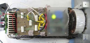
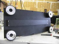
No, I do not see any problem to it. I did it in my recently finished amp:anli said:BTW, if we tell about toroid transformers, are there any drawbacks of a toroid transformer vertical placement? I have not tried yet. Anybody?
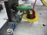
Here is what I did to solve the problem of wiring that needed to go across the whole length. The wires are outside covered with aluminum channel. Dead quiet.
Attachments

I'm about to try to built MC phono preamp (first time 😀).
Anybody got tip how to make clean and quiet supply for MC? Is it always needed to separate the box for the supply from the audio?
Anybody got tip how to make clean and quiet supply for MC? Is it always needed to separate the box for the supply from the audio?
Nelson Pass said:You can move a toroid around, orienting it various ways and
get some improvement, but there's always some noise, and
unfortunately the noise is not necessarily consistent from
transformer to transformer for even the best manufacturers.
The most certain solution is raw distance.
😎
Thanks Nelson. What has your experience been with using different types of rectifiers?
Bob
lumanauw said:MC phono pre
Not necessary, but why make life difficult if you can stick the EI !transformer in a little alloy box, also makes the actual mc-pre chassis smaller.
Attachments
Bob Cordell said:OK, suppose we are stuck with a given transformer, which may often be the case. How can we reduce this tendency to radiate a spray of 120 Hz harmonics? Is there some kind of better filtering we can do at or near the ac side of the rectifiers? Will soft-recovery diodes help this? I've tried snubbing and shunt capacitance with limited improvement. Its just surprizing that the toroid was so much more prone to this than a conventional transformer.
Bob
In the Gary Galo "Pooge 5.5 DAC960 Modifications" (TAA 1/94) Rick Miller described some work he did on 1n4xxx diodes contrast with BYV28-100 and GI851 -- he didn't do any empirical work on the HexFreds -- the work showed considerably less RFI noise for the high speed/soft recovery diodes.
He used an AD811 cfb opamp at +20dB into 50R coupled with 100nF -- and a Tek 2710 spec analyzer -- although for this application you can probably see the noise over a few MegaHertz.
...and the XYL tells me I have to get rid of these magazines...
don't know if somebody mentions it yet
This may increase rfi problems.
Regards
due to the smaller output impedance it will deliver larger current spikes into the charging capacitor.Its just surprizing that the toroid was so much more prone to this than a conventional transformer.
This may increase rfi problems.
Regards
Bob Cordell said:What has your experience been with using different types of rectifiers?
Fast rectifiers and high frequency filtering measurably improve
radiated noise, enough to make the difference between passing
and failing EMI testing in many countries.
Historically I have remained sceptical about the sonic benefits,
but I have a couple of people who can hear a difference in a
single-blind test. I haven't gotten too excited, as the decision to use the parts is moot (as above).
😎
Nelson Pass said:
Fast rectifiers and high frequency filtering measurably improve
radiated noise, enough to make the difference between passing
and failing EMI testing in many countries.
Historically I have remained sceptical about the sonic benefits,
but I have a couple of people who can hear a difference in a
single-blind test. I haven't gotten too excited, as the decision to use the parts is moot (as above).
😎
Thanks, Nelson, good point. EMI requirements can indeed be a tough pain. We recently had a 16-layer daughterboard where we had to plate the board edges to reduce emissions at 6 GHz. That stuff can squeek through a crack like a termite.
Cheers,
Bob
Hello all
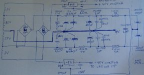
Please help me with this PSU design. I'm not sure if the common 0v for VAS and LTP is correct connected to the main GND
The SR for first stages will be standard zener + bjt serial regulators.
The last 1000uF low ESR capacitors will be as close as possible to the output BJTs and the amp's PCB will be designed with internal starground
All suggestions are welcome
Mihai
Attachments
- Status
- Not open for further replies.
- Home
- Amplifiers
- Solid State
- Bob Cordell Interview: Power Supplies