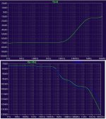
A simple study case, my simple "one stage" amplifier, folded cascode, has very poor PSRR at freq over 10kHz (see figure, above graph).
The second graph in the attached picture is the PSRR graph of the "super regulator" which is presented in the next post.
Shall I presume that the final PSRR will be the superimposed figure?
The second graph in the attached picture is the PSRR graph of the "super regulator" which is presented in the next post.
Shall I presume that the final PSRR will be the superimposed figure?
Attachments
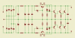
roender said:Super regulator principle schematic
Roender,
Not trying to rain on your parade, but that is not a superreg. All the superreg variations, its predecessor and followers had one thing in common: they use a feedback loop with an error amp. In this sense, that circuit isn't a regulator at all.
The term superreg isn't trademarked AFAIK, but calling all power supplies 'superregs' DOES cause confusion.
To your question: I would expect the figures to add ONLY if all the wiring, parasitics and mutual couplings were taken care of. I expect in reality that the result is less than the sum of the parts.
Jan Didden
janneman said:
Hi Kevin,
There are several issues here mixing themselves up. Firstly, using a 2SC3281 for low current applications (100mA?) doesn't make sense for the reason you mentioned. BUT if you need a high current reg (say for a class A amp) that 2SC3281 does make sense and the low beta at low Ic issue goes away. In the 'superreg' a lot of people use those D44-types and they have good gain linearity at lower currents.
If you use the right BJT for a 'superreg', changing it out for a mosfet will most probably lead to lower loop gain and lower performance but I know I shouldn't make blanket statements here without knowing all the particular circuit details. Another issue with mosfets is the higher drive voltage required although the low-Vgs types may be better here.
Jan Didden
Hello Jan,
Just thought I would reply quickly to your post whilst a large hard disk of mine is taking half an hour to format! 🙂
Regarding the original motorola devices (D44-types) used in the low current version of the super reg. I would need to anaylise the GBP (ft) characteristics of these devices to comment.
A question for you based on your experience.
If the GBP (ft) of some devices is very low at low current (I don't know about the D44's as I ain't seen the Motorola datasheet yet). Add an extremely fast AD797 op amp and I think loop stability could be degraded to be almost unusable. Load a D44 at 10mA or under (intentional) where I think it's Ft is likely to be a lot lower and I wonder what would happen.
The point I am making is, Is it OK to have followers with substantially lower Ft than the op amp in question at low currents in a super reg? (Not sure about this one being honest and it bugs me when I think of designing a high current version)
Obviously, if the follower is loaded at high current (load current, CCS or pre loaded with a R) and gets greater Ft this increases the pole and would be ideal.
The higher drive voltage required for a mosfet is a non issue to me at least, as I would use a voltage doubler anyway and also implement a HQ cascoded CCS for greater Zout. Think there was a lot of consensus about using this approach in the super reg threads - at least in sims, but it couldn't be added to the exisiting PCB. It's the division of the impedance between the CCS and the follower output that sets PSRR.
A real question per se 🙂 Bootstrapping!
If a RC filter was introduced feeding the op amp (still from the output of course) with low R values, would this still benefit from the bootstrapping effect? ie. 30-40db of PSRR and Noise improvement?
I am aware that adding the R component would degrade the ultra low Zout from the output to the error amp and some op amps are fast twitchy devices!. I would also try to get the error amp to drive a mosfet or preload it with an R to minimize the twitchiness if you know what i mean!.
Finally, Have you ever implemented/tried the alternative compensation scheme that was mention in the original AA articles ? Apparently it won't work with a AD797 etc but would with some jfet based op amps. Think it comprises of some RC networks.
All the best
Kevin
PS. Looking forward to your response Jan with baited breath! 🙂
Hi Kevin,
I see you haven't gotten a hold of the original Sulzer article. I don't have it either, unfortunately - so I'm doing this from memory. In that article, he used a 5534 for the op-amp. This device is only stable for a gain of four or greater. Yet he bypassed the feedback resistor from output to inverting input with a large capacitor, making it the equivalent of a gain of one as far as stability is concerned. Further, he introduced a pass transistor into the loop, giving additional phase lag.
Despite all this, the circuit was stable. The key question is "Why?". Was it audiophile magic? What was the mitigating factor here? Is there some kind of "behind the scenes" frequency compensation going on? He did not explain this in his article, probably because he didn't know at the time.
Once you realize the answer to these questions, the whole mystery of "super reg" stability is cleared up. Still, the AD797 is just pushing things too far with its 100 MHz GBW IMHO.
AndrewT said:Controversial is my middle name.
If the PSRR of the amp degrades to -40db @ 100kHz on the negative line and the PSRR of the cheap/easy single chip regulator also degrades to a similar figure @ the same passband frequency, then that is a total attenuation of near 80db on the output.
In the meantime the circuitry of the amp has had to handle all that non-correlated noise while trying to amplify the wanted signal.
I suspect some interaction and that the products of this interaction could be above the -80db level.
Now take your -100db below max output noise figure.
That's not good enough. It's an OK figure but we can do a lot better.
I would try for -90dbW and maybe even set the target at -100dbW.
The noise at the output should then come out as just about inaudible using 100db/Wm speakers (provided there are no exaggerations at any particular freqencies/bands).
Hi Andrew,
I'm glad my Devil's Advocate questions stirred up some discussion.
Note that the amplifier I was using as an example was already rated at 100 dB S/N wrt 1 Watt.
Of course, you are exactly right about PSRR of both the regulator and the amplifier itself degrading at higher frequencies. But this is the easy part to fix with even an IC regulator.
Take an LM337, which is the worse of the two. Its PSRR is as follows:
100 Hz: 75 dB
1 kHz: 65 dB
10 kHz: 50 dB
100 kHz: 30 dB
1 MHz: 10 dB
Now just put a 100 Hz first order RC filter in front of it on the source side:
100 Hz: 78 dB
1 kHz: 85 dB
10 kHz: 90 dB
100 kHz: 90 dB
1 MHz: 90 dB
That can be done with a simple 10 ohm input series resistor and a low-ESR 150 uF electrolytic shunting to ground.
On the output side, we care about Zout. It also degrades to a higher value as frequency increases, as follows (milli-ohms):
100 Hz: 7
1 kHz: 7
10 kHz: 15
100 kHz: 100
1 MHz: 1000
Now put a low-ESR shunt capacitance of 1000 uF in parallel with 1 uF film on the output to ground. It will keep the output impedance below 10 milli-ohms across the full band. As a bonus, that output capacitance acting against the rising output impedance of the regulator further increaes PSRR at high frequencies.
So what is so bad about this inexpensive IC regulator approach? The kind of input and output capacitance I mentioned would probably be there in a quality design anyway, and is certainly simpler than a discrete super regulator. If one wants to get really serious about PSRR of incoming stuff from the power source, one can easily cascade two of these regulators.
Finally, there are many IC regulators out there that are superior to the good old 317/337.
Cheers,
Bob
Bob Cordell said:
So what is so bad about this inexpensive IC regulator approach?
It's boring! 🙂
For a commercial product, fine. For DIY, why not have a bit of fun?
Incidentally, I can’t grasp the fixation with using ultra high OLG / OL bandwidth regulators for audio either. It’s pointless, IMO. It’s simply not a requirement for high PSRR and low output impedance.
Also, most competently designed low-level audio circuits are not “dynamic loads” - they have their current consumption largely defined by current sources. This not only usually provides an inherently high PSRR, but also obviates the requirement for a supply with ultra low, LF output impedance anyway.
Here's a bit of my over-the-top regulator fun:
http://users.picknowl.com.au/~glenk/80VREG.HTM
Very high PSRR and reasonably low output impedance, but with very low open loop bandwidth.
Cheers,
Glen
G.Kleinschmidt said:
It's boring! 🙂
For a commercial product, fine. For DIY, why not have a bit of fun?
Incidentally, I can’t grasp the fixation with using ultra high OLG / OL bandwidth regulators for audio either. It’s pointless, IMO. It’s simply not a requirement for high PSRR and low output impedance.
Also, most competently designed low-level audio circuits are not “dynamic loads” - they have their current consumption largely defined by current sources. This not only usually provides an inherently high PSRR, but also obviates the requirement for a supply with ultra low, LF output impedance anyway.
Here's a bit of my over-the-top regulator fun:
http://users.picknowl.com.au/~glenk/80VREG.HTM
Very high PSRR and reasonably low output impedance, but with very low open loop bandwidth.
Cheers,
Glen
Amen on all counts!
Thanks,
Bob
Fanuc said:Hello Jan,
A question for you based on your experience.
If the GBP (ft) of some devices is very low at low current (I don't know about the D44's as I ain't seen the Motorola datasheet yet). Add an extremely fast AD797 op amp and I think loop stability could be degraded to be almost unusable. Load a D44 at 10mA or under (intentional) where I think it's Ft is likely to be a lot lower and I wonder what would happen.
{snip]
I guess I agree to that. It is one of the reasons why in the original article I went on record to advise against using the 797 here because of these factors. The stability depended too much on the particular operating conditions ie load current.
Fanuc said:[snip]PS. Looking forward to your response Jan with baited breath! 🙂
I don't think that's a good career move 😉
Jan Didden
andy_c said:Hi Kevin,
I see you haven't gotten a hold of the original Sulzer article. I don't have it either, unfortunately - so I'm doing this from memory. In that article, he used a 5534 for the op-amp. This device is only stable for a gain of four or greater. Yet he bypassed the feedback resistor from output to inverting input with a large capacitor, making it the equivalent of a gain of one as far as stability is concerned. Further, he introduced a pass transistor into the loop, giving additional phase lag.
Despite all this, the circuit was stable. The key question is "Why?". Was it audiophile magic? What was the mitigating factor here? Is there some kind of "behind the scenes" frequency compensation going on? He did not explain this in his article, probably because he didn't know at the time.
Once you realize the answer to these questions, the whole mystery of "super reg" stability is cleared up. Still, the AD797 is just pushing things too far with its 100 MHz GBW IMHO.
The 'magic' here was the output capacitor that modified the loop sufficiently to make it stable. Output caps have been a designers headache especially in low drop out regs with a PNP pass transistor. For board space reasons you would like to do away with it, but for stability reasons you need it (and you need some non-zero ESR as well). Years ago one manufacturer advertised with low dropout regs that were stable with small-footprint, low-esr ceramic caps. Important enough to highlight it in the ads.
Hi Glen,G.Kleinschmidt said:
It's boring! 🙂
For a commercial product, fine. For DIY, why not have a bit of fun?
Incidentally, I can’t grasp the fixation with using ultra high OLG / OL bandwidth regulators for audio either. It’s pointless, IMO. It’s simply not a requirement for high PSRR and low output impedance.
Also, most competently designed low-level audio circuits are not “dynamic loads” - they have their current consumption largely defined by current sources. This not only usually provides an inherently high PSRR, but also obviates the requirement for a supply with ultra low, LF output impedance anyway.
Here's a bit of my over-the-top regulator fun:
http://users.picknowl.com.au/~glenk/80VREG.HTM
Very high PSRR and reasonably low output impedance, but with very low open loop bandwidth.
Cheers,
Glen
In the link you provided, I can't see any connection from the pos pass transistor emitter to the output, except through that lowly BD139? Or is this a low-current design for pre-stages?
Jan Didden
janneman said:
Hi Glen,
In the link you provided, I can't see any connection from the pos pass transistor emitter to the output, except through that lowly BD139? Or is this a low-current design for pre-stages?
Jan Didden
Yes, it is a low current design, for this:
http://users.picknowl.com.au/~glenk/MAIN.HTM
The BD681 darlington dissipates the majority of the power and is a cascode for the BD139, with it's base referenced to the regulated output. Vce for the BD139 is effectively bootstrapped at ~4.2V. The improves the PSRR by keeping the collector voltage of the BD139 "clean".
The BD681/BD682 transistors have a much higher max Ic than required, but they're as cheap as chips and easy apply in this circuit due to their high hfe.
Cheers,
Glen
jackinnj said:'must be rainining in land locked Luxembourg 🙂
Hey Jack!
Where have you been all that time? Good to see you back - if only to mock me 😉
PS I am no longer in Lux. See below my avatar.
Jan Didden
Bob Cordell said:
Amen on all counts!
Thanks,
Bob
Hey, if you like my sermons, you may consider a monetary donation into my bank account. But don’t be frugal, lest you be shown up as insincere.

Cheers,
Glen
janneman said:
Years ago one manufacturer advertised with low dropout regs that were stable with small-footprint, low-esr ceramic caps. Important enough to highlight it in the ads.
I know this was the AnyCap range of LDO reg's
This was the reason I asked you the question up north about whether you had tried the alternative compensation method suggested in the Superreg articles (RC filters) that may permit this approach or using very large caps.
Apparently using pole splitting is fairly easy implemented but degrades the PSRR or introduces alot of noise etc and hence the problem with it. The AnyCap design circumvents this. Sure I have seen IEEE references/articles about this also.
Having said that the Zout of the '95 AD797 Reg is so low it is doubtful they would do anything under 1mhz!.
Kevin
this time the context does not help me to clarify whether you mean milli Hertz or Mega Hertz.Fanuc said:.........Having said that the Zout of the '95 AD797 Reg is so low it is doubtful they would do anything under 1mhz!.
Please tell me which?
Bob Cordell said:
But this is the easy part to fix with even an IC regulator.
Take an LM337, which is the worse of the two. Its PSRR is as follows:
100 Hz: 75 dB
1 kHz: 65 dB
10 kHz: 50 dB
100 kHz: 30 dB
1 MHz: 10 dB
Now just put a 100 Hz first order RC filter in front of it on the source side:
100 Hz: 78 dB
1 kHz: 85 dB
10 kHz: 90 dB
100 kHz: 90 dB
1 MHz: 90 dB
That can be done with a simple 10 ohm input series resistor and a low-ESR 150 uF electrolytic shunting to ground.
On the output side, we care about Zout. It also degrades to a higher value as frequency increases, as follows (milli-ohms):
100 Hz: 7
1 kHz: 7
10 kHz: 15
100 kHz: 100
1 MHz: 1000
Now put a low-ESR shunt capacitance of 1000 uF in parallel with 1 uF film on the output to ground. It will keep the output impedance below 10 milli-ohms across the full band. As a bonus, that output capacitance acting against the rising output impedance of the regulator further increaes PSRR at high frequencies.
Cheers,
Bob
Hello Bob,
Just want to comment on your figures above.
The PSRR specs of the LM337 you mention is specified at a Load current of 500mA on the datasheet (where it's OLG is much higher) - a most unlikely condition for a power amp VAS and I/P stage. So the PSRR specs should be dropped by 20db (1/10th the current) at least at all frequency's.
The Zout figures you mention do not mention the PCB layout resistances etc and grounding (plus an artificiallly high OLG for Power amp driver stage purposes). These could destroy these figures instantly.
You have also failed to mention the reduction of performance of teeing off the common tab to boost voltage - adding zeners etc. I must admit I don't really know much of the affect this has on the performance of the Reg..
Someone quite canny once said that a datasheet is more of a advertisement for the manufacturers devices - the devices are shown in there best light etc. And I concur.
Now on to the specs of the RC filter used prior to the reg etc. Was this simulated with Pspice? or measured with an AP system 1 or 2 ? . I've found the best caps for low ESR are at low voltage.
Measuring 90db PSRR at 1 mhz isn't going to be easy I would of thought.
All the best
Kevin
AndrewT said:this time the context does not help me to clarify whether you mean milli Hertz or Mega Hertz.
Please tell me which?
MegaHertz (MHz)
Fanuc said:
Hello Bob,
Just want to comment on your figures above.
The PSRR specs of the LM337 you mention is specified at a Load current of 500mA on the datasheet (where it's OLG is much higher) - a most unlikely condition for a power amp VAS and I/P stage. So the PSRR specs should be dropped by 20db (1/10th the current) at least at all frequency's.
The Zout figures you mention do not mention the PCB layout resistances etc and grounding (plus an artificiallly high OLG for Power amp driver stage purposes). These could destroy these figures instantly.
You have also failed to mention the reduction of performance of teeing off the common tab to boost voltage - adding zeners etc. I must admit I don't really know much of the affect this has on the performance of the Reg..
Someone quite canny once said that a datasheet is more of a advertisement for the manufacturers devices - the devices are shown in there best light etc. And I concur.
Now on to the specs of the RC filter used prior to the reg etc. Was this simulated with Pspice? or measured with an AP system 1 or 2 ? . I've found the best caps for low ESR are at low voltage.
Measuring 90db PSRR at 1 mhz isn't going to be easy I would of thought.
All the best
Kevin
Hi Kevin,
You make some good points that raise some questions.
On what basis do you assert that the PSRR of the LM337 degrades by 20 dB when the load current is reduced from 500 mA to 50 mA? I am not an expert on the design and behavior of the LM337, but I have no reason to believe that this is so. Please explain.
Of course PCB layout resistances and layout will affect Zout adversely, especially if a poor job is done. But this will be so for any regulator design, including super regulators.
"(plus an artificiallly high OLG for Power amp driver stage purposes). These could destroy these figures instantly." Please be more specific about what you mean here.
"You have also failed to mention the reduction of performance of teeing off the common tab to boost voltage - adding zeners etc." Please be more specific here as well.
I do not concur with your skeptical view of manufacturers and their spec sheets. Most of them try very hard to be accurate, but it is not always possible to cover every application, for want of space, if nothing else. Yes, it would have been nice if National also showed all of their spec sheet data at a load current of 50 mA as well. You as a designer also have a certain responsibility to characterize the device's suitability to your own application. One can't fully depend on the data sheet, but this is not a reason to throw the baby out with the bathwater or to accuse the manufacturer of merely making up a data sheet for marketing purposes.
I assume you refer to the LPF I suggested putting in front of the LM337 to improve its PSRR at high frequencies. This was neither simulated nor measured. It was simply based on a back-of-the-envelope calculation of what additional attenuation to incoming interference the LPF would provide.
Cheers,
Bob
- Status
- Not open for further replies.
- Home
- Amplifiers
- Solid State
- Bob Cordell Interview: Power Supplies