Hi Edmond,
Very clever!
BTW, wrt the peak with the bootstrapped diamond buffer, I have some feeling that the speedup capacitor C6 exacerbates it by closing a positive feedback loop at HF around each cascaded EF pair. Without C6, each predriver collector just gets a feedforward bootstrapped signal from the other (somewhat independent) side. Without C6, and with some resistance in series with each predriver base, I think the peaking is mitigated. Just a thought.
Cheers,
Bob
Hello Bob
If we take out C6 we can use, as speedup capacitors, 470 nF capacitors across the output base resistors ?
Years ago Naim used that way of speedup capacitor, but in a different amp topology.
Bye
Gaetan
I'm afraid that appealing to Bob or anybody else won't help when you're looking straight at the fundamental limits of negative feedback
minimum phase is required for maximum applied feedback - all pass "phase correction" is not minimum phase
I keep pointing to B.J. Lurie's work for a reason - it is unusual in showing how to apply Bode integrals to feedback, illustrating the limits
the phase dip is an explicit cost of using higher order gain slope - can't be avoided
higher order loop gain slopes enable more audio frequency loop gain - because the "area" of frequency*ln|F| of the negative feedback region is fixed by the stability limit - so having it "poke up" higher in the audio frequency range implies getting lower faster at higher frequencies to meet the gain phase margins
Bode integrals are useful tools - at a high level they tell you what can/cannot be done with negative feedback
http://trs-new.jpl.nasa.gov/dspace/bitstream/2014/19495/1/98-0905.pdf
Lurie's site is gone but lives on in the WayBack Machine:
Classical Feedback Control, Chapter 4: Shaping the Loop Frequency Response
Mitchell covers some of the same territory:
Dr Richard Mitchell's Selected Research Papers and Presentations
Interesting link you posted, if you want to learn more about the subject of control theory have material from the author Dr. Katusuhiko Ogata, are several volumes and belong to a university in your country (I do not remember which now).
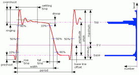
In theory control theory has enough to deal with the unstable system, through the ramp response you write down the values of the oscillation ( Fig attached) to implement the gain proportional, derivative and integral it can be in series or parallel...but control system is slow, different from the amp audio.
In the little knowledge I have about the stability of audio amplifiers, I identified two controls. Derivative, being the input filter RF and output inductor (with shunt resistor) that acts to reduce the rise time of the amp giving a response dampening, another was the integrative, circuit formed by RC in global NFB network which is used to minimize the role of the second pole, I do not know what effect it will have a second pole of higher order than the dominant pole in the square wave response.
Attachments
Hi Edmond,
Very clever!
Thank you !
BTW, wrt the peak with the bootstrapped diamond buffer, I have some feeling that the speedup capacitor C6 exacerbates it by closing a positive feedback loop at HF around each cascaded EF pair. Without C6, each predriver collector just gets a feedforward bootstrapped signal from the other (somewhat independent) side. Without C6, and with some resistance in series with each predriver base, I think the peaking is mitigated. Just a thought.
Cheers,
Bob
Hi Bob,
Indeed, interesting thought. So I removed C6 to see what happens. Regrettably, the peaking was sill there. Next, I put 100R base stoppers in front of the pre-drivers. This only worsens the peaking. Actually, not that amazing, as it is equivalent to increasing Ri by 50R, which appears to have about the same effect.
(Probably needless to mention, C6, being a speedup cap, can be found in almost every OPS.)
Cheers,
E.
http://www.diyaudio.com/forums/soli...terview-negative-feedback-50.html#post1160022
why is it essential to have an EF enhanced VAS for TMC to work?
why is it essential to have an EF enhanced VAS for TMC to work?
Hi Andrew,
For two reasons: TMC is only effective if the VAS has sufficient gain* and if the distortion of the VAS is markedly lower than the distortion of the OPS. The so called 'beta enhancement' transistor in front of the VAS addresses both requirements.
Cheers,
E.
edit: * TMC is aimed to increase the loop gain around the OPS. The additional gain has to come from somewhere, that's why you need it.
Last edited:
can other VAS topologies meet those two criteria?
eg. a cascoded VAS with EF buffer?
Or must it be the VAS with EF pre buffer?
eg. a cascoded VAS with EF buffer?
Or must it be the VAS with EF pre buffer?
Of course, but alt least a pre-buffer or a cascode. Both will reduce the distortion, though the latter does a better job (at the expense of some output swing). See also D. Self on this topic.
edit: For a more exact answer you better simulate your amp and compare the distortion from different topologies.
Cheers,
E.
edit: For a more exact answer you better simulate your amp and compare the distortion from different topologies.
Cheers,
E.
Last edited:
that will naturally follow once I have learned to understand the language you and the other experts use.For a more exact answer you better simulate your amp and compare the distortion from different topologies.
I need to understand the operation, before I can ask the simulator the correct questions to get meaningful answers.
In the meantime, thanks for tolerating my slow pace of learning.
that will naturally follow once I have learned to understand the language you and the other experts use.
I need to understand the operation, before I can ask the simulator the correct questions to get meaningful answers.
In the meantime, thanks for tolerating my slow pace of learning.
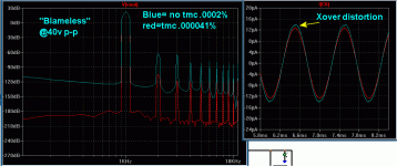
I'm no expert , But I see what TMC does to the operation of the typical high loop gain amp. (attachment 1) is a typical "blameless" @ over 90db LG... plotted without and with TMC. The blue is good at .0005% , but on the second part of the plot (blue C6 - miller cap), you see that little "notch" at the top of the waveform. Lining this up with my output's current plot , the notch corresponds to the crossover point. On the red TMC'ed plot(s) ,you see the much lower harmonic and the notch is GONE on C6. I can only assume that TMC's local feedback is cancelling out the crossover distortion that is being fed back globally. C6 plot and the FFT clearly show this.
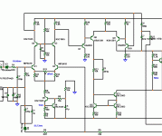
On a slightly lower loop gain amp , TMC has a more subtle but very desirable effect. On (Attachment 2) , is a beta enhanced symasym (Attachment-3 / 75db+). It also loses 20db or more on the high harmonic distortion components. The lower loop gain translates directly to less of a global reduction in distortion but still a very desirable reduction in higher order components.
I tried TMC on my low loop gain LUXMAN (gx) and the original symasym ... both in simulation and for real .. no or very little effect. I also found that 60 or more DB is the point where TMC has a noticeable effect.
OS
Attachments
if VAS is an hFE ~200 transistor then TMC does not work well.
If the beta enhanced VAS uses transistors of hFE~200 & 160 (total current gain ~32k) then TMC can work well.
What if the Beta enhanced VAS uses low hFE transistors for a total current gain of ~10k? Does this become borderline? or does 10k>>200 satisfy the VAS gain requirement?
If the beta enhanced VAS uses transistors of hFE~200 & 160 (total current gain ~32k) then TMC can work well.
What if the Beta enhanced VAS uses low hFE transistors for a total current gain of ~10k? Does this become borderline? or does 10k>>200 satisfy the VAS gain requirement?
if VAS is an hFE ~200 transistor then TMC does not work well.
If the beta enhanced VAS uses transistors of hFE~200 & 160 (total current gain ~32k) then TMC can work well.
What if the Beta enhanced VAS uses low hFE transistors for a total current gain of ~10k? Does this become borderline? or does 10k>>200 satisfy the VAS gain requirement?
What matters is the AC voltage gain of the VAS not the hfe
of the relevant bjts..
Part of this gain is used to implement a local negative feedback loop
comprising the said VAS and the OPS.
tried TMC on ... the original symasym ... both in simulation and for real .. no or very little effect.
TMC is only effective if the VAS has sufficient gain* and if the distortion of the VAS is markedly lower than the distortion of the OPS.
Thank you OS for independent confirmation of VAS spec for TMC implementation
if VAS is an hFE ~200 transistor then TMC does not work well.
If the beta enhanced VAS uses transistors of hFE~200 & 160 (total current gain ~32k) then TMC can work well.
What if the Beta enhanced VAS uses low hFE transistors for a total current gain of ~10k? Does this become borderline? or does 10k>>200 satisfy the VAS gain requirement?
"Total AC gain".. how you get there is of no matter. The KSA1381 and KSA992 both model as a Hfe 100 device. In real life, gain group "F" does likewise. So at 10K Hfe we are not "borderline" ... in fact my AX "blameless" (attachment1) is at 100db even with large degeneration resistors at the input pair. (Attachment 2) shows the low gain luxman with its single ksa1381 (hfe100-135) , this amp will not work (well) with TMC , it has no "extra" loop gain to "burn". Conversely , a VERY high gain single VAS device might show an improvement with TMC , but you would then be loading down the input stage .. increasing distortion anyways.
OS
Attachments
Thank you OS for independent confirmation of VAS spec for TMC implementation
Hi Dimitri,
Your point is well-taken, but I also think that its true that people will usually employ TMC to further improve an amplifier that already has a very good VAS. In such an amplifier, the output stage inevitably establishes the ultimate performance level in terms of amount of distortion and the order of the distortion components.
So I think in most cases where we are discussing TMC, it almost goes without saying that we have a Darlinton VAS with a good VAS transistor, and that we probably have an output Triple. These two inexpensive circuit features virtually guarantee a circuit environment where TMC will be quite effective.
Cheers,
Bob
Hi Robert,
I had in mind that TMC will work well with Darlington VAS/ triple EF. Thank you for accentuating this. OS confirmed that for low-gain/high-disto VAS TMC wouldn't be an optimum.
I'm afraid, there is one more requirement. There is no more pole-splitting for the pole, associated with the output node of VAS. To make the time constant of this pole as low as possible additional measures should be taken as Hawksford/Baxandall/Tektronix cascode in VAS, input pair of triple EF with low input capacitance (floating cascodes, floating shield, etc.)
The second "real life" TMC creation was independently built and tested.

Builder was very happy with sound quality . 🙂
http://www.diyaudio.com/forums/solid-state/169590-mongrel-supersym-ii-17.html#post2377235
TMC is here to stay for my blameless based voltage stages. As far as running a triple , good idea.... but , my mje15032/33 -njw0281/0302 EF2 has sufficient current gain with 4-8R loads and performs quite well even with multiple pair OP's.
OS
Hi Robert,
I'm afraid, there is one more requirement. There is no more pole-splitting for the pole, associated with the output node of VAS. To make the time constant of this pole as low as possible additional measures should be taken as Hawksford/Baxandall/Tektronix cascode in VAS, input pair of triple EF with low input capacitance (floating cascodes, floating shield, etc.)
Hi Dimitri
Thanks for a very interesting post.
I have searched this forum for more info, but could not find anything; I have also made a Google search for “Tektronix cascode” and the combination “tmc hawksford vas”, but couldn’t find anything that I didn’t already knew.
Maybe this is related to your own observations and analysis.
If so, I understand that you are not interested to share them on an open forum like this.
If that’s not the case, could you please post some links for further reading?
Thanks
stinius
Hi Robert,
I had in mind that TMC will work well with Darlington VAS/ triple EF. Thank you for accentuating this. OS confirmed that for low-gain/high-disto VAS TMC wouldn't be an optimum.
I'm afraid, there is one more requirement. There is no more pole-splitting for the pole, associated with the output node of VAS. To make the time constant of this pole as low as possible additional measures should be taken as Hawksford/Baxandall/Tektronix cascode in VAS, input pair of triple EF with low input capacitance (floating cascodes, floating shield, etc.)
Hi Dimitri,
With regard to pole splitting at the output node of the VAS, I believe that it is still there at frequencies above the TMC transition frequency, where in my opinion it is most important (I am assuming in this simple case that the TMC is picked off from the VAS collector, not the predriver). Anyway, I don't see a reason why a cascoded VAS is needed for use with TMC.
Cheers,
Bob
Mystifying TMC
Some Ph.D 'over there' (let's call her Ophelia) has tried to analyze TMC by means of old school pen and paper math. Here follows a few of Ophelia's conclusions:
> In fact, the phase dip is not cancelled in any way (that would actually be impossible for a second order system)
> but because the remaining gain available to wrap (and linearize) the VAS is greatly reduced (and hence so is the phase dip).

Indeed, that would be impossible for a second order system. The real reason for the absence of a phase dip lies in the fact that TMC is NOT a second order system. The difference between TPC and TMC is that TPC acts on the whole signal of the VAS output, while TMC acts on the difference between OPS output and VAS output, i.e. the error signal from the OPS.
So, one might say that only the error signal is "TPCed". As this signal is only a small fraction of the whole signal, the increase in order (due to TMC) is also a small fraction compared to a 2nd order system like TPC. If, for example, the error signal is 2% (which is equivalent to a OPS gain of 0.98), then the 'order' is 1.02. That is the reason why there is (almost) no phase dip and overshoot. (This also means that the lower the OPS gain, the more phase dip and overshoot. )
> On the flip side, TMC extra loads the input stage, with the equivalent lead-lag compensation network Miller reflection. For identical global amp
> results, this may require a beefier input stage (more current, more degeneration, etc...) compared to simple Miller or TPC compensation.

Is that So? Let's have a look at the (simmed) output current of the input stage for a typical blameless amp with respectively Miller, TPC and TMC compensation. f=100kHz and Vi=1V
Miller: 261.0nA
TPC: 265.9nA
TMC: 260.5nA
So TMC results in the lowest IPS output current of all of the three compensation schemes. Needless to say that I've no trouble with this alleged 'flip side'. 😀
Bottom line: Never trust pen and paper math. Always verify the results by means of simulation.
Cheers,
Edmond.
Some Ph.D 'over there' (let's call her Ophelia) has tried to analyze TMC by means of old school pen and paper math. Here follows a few of Ophelia's conclusions:
> In fact, the phase dip is not cancelled in any way (that would actually be impossible for a second order system)
> but because the remaining gain available to wrap (and linearize) the VAS is greatly reduced (and hence so is the phase dip).

Indeed, that would be impossible for a second order system. The real reason for the absence of a phase dip lies in the fact that TMC is NOT a second order system. The difference between TPC and TMC is that TPC acts on the whole signal of the VAS output, while TMC acts on the difference between OPS output and VAS output, i.e. the error signal from the OPS.
So, one might say that only the error signal is "TPCed". As this signal is only a small fraction of the whole signal, the increase in order (due to TMC) is also a small fraction compared to a 2nd order system like TPC. If, for example, the error signal is 2% (which is equivalent to a OPS gain of 0.98), then the 'order' is 1.02. That is the reason why there is (almost) no phase dip and overshoot. (This also means that the lower the OPS gain, the more phase dip and overshoot. )
> On the flip side, TMC extra loads the input stage, with the equivalent lead-lag compensation network Miller reflection. For identical global amp
> results, this may require a beefier input stage (more current, more degeneration, etc...) compared to simple Miller or TPC compensation.

Is that So? Let's have a look at the (simmed) output current of the input stage for a typical blameless amp with respectively Miller, TPC and TMC compensation. f=100kHz and Vi=1V
Miller: 261.0nA
TPC: 265.9nA
TMC: 260.5nA
So TMC results in the lowest IPS output current of all of the three compensation schemes. Needless to say that I've no trouble with this alleged 'flip side'. 😀
Bottom line: Never trust pen and paper math. Always verify the results by means of simulation.
Cheers,
Edmond.
Last edited:
- Home
- Amplifiers
- Solid State
- Bob Cordell Interview: Negative Feedback


