there's more...for the benefit of SY
>>>From his record collection, Charles picked Kraftwerk's 1978 Mensch-Maschinen (The Man Machines), an old, well played example of techno Krautrock. The opening song "The Robot" -- wir sind die Robotor
Excusing the bad translation this is the second LP to have "the last veils removed" by demagnetization.
It has been argued in the "feedback question/clarification thread" that the application of negative feedback to amplifier circuits creates new, higher-order distortion products, or increases those already present. This assertion comes up a couple of times a year on this board. Some of this comes from Baxandall’s experiments with single stage amplifers where distortion of numerous orders was examined as a function of the amount of NFB applied.
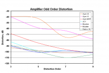
But what of this effect in real power amplifiers? Here we look at actual Stereophile review measurements for several amplifers that range from no-feedback designs to high-feedback designs.
Specifically, we look at the odd-order CCIF IM components from third order to 9th order. These are readily observable from the CCIF IM spectral plots. Unlike with THD-20, the lower sidebands of the 19 + 20 kHz CCIF IM test lie in-band, from 18 kHz on down at 1 kHz intervals. These sidebands are reflective of odd-order distortions. For example, 3rd order non-linearities produce a sideband at 18 kHz, while 5th order non-linearities produce a sideband at 17 kHz and so on.
The results are shown in the graph below.
The no-feedback Ayre V1 and V3 produce high levels of distortion out to quite high orders. These two poor performers single-handedly destroy the generalization that negative feedback is more likely to lead to higher-order distortions.
In contrast, the newer Ayre MXR is remarkably and unusually good for a no-feedback amplifier. Note that for 7th through 11th, the no-feedback MXR is just about as good as the Parasound JC-1. It still falls short of the designs using NFB for 3rd and 5th order distortions.
The high-feedback Bryston, Boulder and Halcro amplifiers do much better in the 3rd and 5th order departments without giving up any ground in the 7th through 9th departments to the amplifiers with no feedback or less feedback.
The point here is that the pseudo-technical generalization that NFB increases high-order distortions in power amplifiers is simply wrong.
Cheers,
Bob
Attachments
BJT Distortion as a function of NFB
There has been a debate raging over on the “feedback question/clarification” thread about whether the application of negative feedback introduces or exacerbates high-order distortion products. This debate is put forth about twice a year by those who believe that the use of negative feedback makes amplifiers sound bad. The one good thing about this argument is that it can be tested objectively, both by simulation and measurement of real amplifiers.
This argument largely springs from the work of Baxandall, who showed this effect to be true under a particular set of conditions for single-stage JFET and BJT amplifiers. While Baxandall’s work was correct, and gives pause for designers, it has largely been wrongly generalized to be an indictment of negative feedback.
The effect is real and understandable. If you pass a signal through a nonlinearity and then feed some of that signal back, the original signal and the distorted fed-back signal will intermodulate in the nonlinearity and may create new spectra.
The effect is especially well illustrated when the nonlinearity is a pure second order nonlinearity. With no feedback, you only get second harmonic at the output. With feedback, you get re-circulation ad-nausium, creating harmonics out to very high orders (albeit of rapidly descending amplitude as order increases).
Of course, devices like BJTs have an exponential nonlinearity that already produces distortion products out to high orders, even without negative feedback.
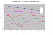
The graphs in the following posts show 2nd through 7th order distortion of a single-stage BJT as a function of amount of negative feedback applied to it. In all cases the output level is the same 3V peak.
The first graph below shows the case for a BJT stage with no emitter degeneration. This is most analogous to what Baxandall did. We clearly see that 4th through 7th order distortions increase as NFB is applied – at least initially!
Beyond about 20 dB of NFB, all of the distortions are decreasing as more NFB is applied. However, note that even at 30 dB NFB, the higher-order 5th through 7th spectra are still at amplitudes that are higher than the (admittedly small) starting values with no negative feedback. So there is certainly at least a grain of truth to the assertions about the application of NFB exacerbating high-order distortion spectra. But is it a half-truth?
Cheers,
Bob
There has been a debate raging over on the “feedback question/clarification” thread about whether the application of negative feedback introduces or exacerbates high-order distortion products. This debate is put forth about twice a year by those who believe that the use of negative feedback makes amplifiers sound bad. The one good thing about this argument is that it can be tested objectively, both by simulation and measurement of real amplifiers.
This argument largely springs from the work of Baxandall, who showed this effect to be true under a particular set of conditions for single-stage JFET and BJT amplifiers. While Baxandall’s work was correct, and gives pause for designers, it has largely been wrongly generalized to be an indictment of negative feedback.
The effect is real and understandable. If you pass a signal through a nonlinearity and then feed some of that signal back, the original signal and the distorted fed-back signal will intermodulate in the nonlinearity and may create new spectra.
The effect is especially well illustrated when the nonlinearity is a pure second order nonlinearity. With no feedback, you only get second harmonic at the output. With feedback, you get re-circulation ad-nausium, creating harmonics out to very high orders (albeit of rapidly descending amplitude as order increases).
Of course, devices like BJTs have an exponential nonlinearity that already produces distortion products out to high orders, even without negative feedback.
The graphs in the following posts show 2nd through 7th order distortion of a single-stage BJT as a function of amount of negative feedback applied to it. In all cases the output level is the same 3V peak.
The first graph below shows the case for a BJT stage with no emitter degeneration. This is most analogous to what Baxandall did. We clearly see that 4th through 7th order distortions increase as NFB is applied – at least initially!
Beyond about 20 dB of NFB, all of the distortions are decreasing as more NFB is applied. However, note that even at 30 dB NFB, the higher-order 5th through 7th spectra are still at amplitudes that are higher than the (admittedly small) starting values with no negative feedback. So there is certainly at least a grain of truth to the assertions about the application of NFB exacerbating high-order distortion spectra. But is it a half-truth?
Cheers,
Bob
Attachments
BJT distortion vs emitter degeneration
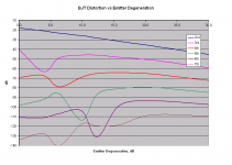
Now let’s look at the same BJT stage wherein we apply the negative feedback simply by means of emitter degeneration. This is a very important case because emitter degeneration is seen as benign by the no-feedback camp, and is given special dispensation by them. Most so-called no-feedback amplifiers depend extensively on the linearizing properties of emitter degeneration.
Remarkably, the curves look very much like those in the last post! But why should we be surprised, after all? The theory is the theory. Nevertheless, even I was surprised by this result. The application of negative feedback, even by means of benign emitter degeneration increases the production of high-order distortions. So if this Baxendall phenomena is making NFB bad, then the so-called no-NFB designs are suffering from it just as well!
Cheers,
Bob
Attachments
Hi Bob,
That's a quite clear set of data! Thanks for that.
BTW, I guess these feedback amps all have relatively high feedback?
Merry Christmas to you and your loved ones🙂 !
Jan Didden
That's a quite clear set of data! Thanks for that.
BTW, I guess these feedback amps all have relatively high feedback?
Merry Christmas to you and your loved ones🙂 !
Jan Didden
BJT Distortion with emitter degen and NFB
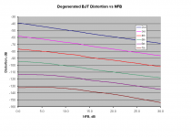
Now finally let’s look at the application of NFB around a degenerated BJT stage. This is important because the degenerated BJT stage is the usual starting point for both no-feedback and properly-executed feedback designs. This, I assert, is the legitimate level playing field.
The graph below is for a BJT stage emitter-degenerated by about 20 dB, or a factor of about 10 in gain. BJT’s have plenty of transconductance, so I usually throw 90% of it away in the common-emitter configuration with 10:1 degeneration.
Now we see that distortion of all orders decreases monotonically as NFB is increased. Here we see the wisdom of building a reasonably linear amplifier and only then putting global feedback around it. Notice that the scale in this graph extends down to –160 dB.
We note that the forward path of an amplifier usually has about three stages with numerous different nonlinearities, so higher-order distortions develop even without NFB. Even an amplifier with only three stages, each with a pure second-order nonlinearity, will start out with distortion spectra out to the sixth order. Moreover, the crossover distortion produced by Class-AB output stages extends out to very high orders due to the switching nature of the crossover transition.
Cheers,
Bob
Attachments
Re: BJT distortion vs emitter degeneration
Hi Bob,
Excellent work and very informative.
Feedback is feedback. You hit the nail on the head.
BTW, HEC too! 😀
Cheers Edmond.
Bob Cordell said:Now let’s look at the same BJT stage wherein we apply the negative feedback simply by means of emitter degeneration. This is a very important case because emitter degeneration is seen as benign by the no-feedback camp, and is given special dispensation by them. Most so-called no-feedback amplifiers depend extensively on the linearizing properties of emitter degeneration.
Remarkably, the curves look very much like those in the last post! But why should we be surprised, after all? The theory is the theory. Nevertheless, even I was surprised by this result. The application of negative feedback, even by means of benign emitter degeneration increases the production of high-order distortions. So if this Baxendall phenomena is making NFB bad, then the so-called no-NFB designs are suffering from it just as well!
Cheers,
Bob
Hi Bob,
Excellent work and very informative.
Feedback is feedback. You hit the nail on the head.
BTW, HEC too! 😀
Cheers Edmond.
Hi Bob,
Thanks for posting that.
In the recent past when this subject has come up, I've tried linking to the part of this thread where this was originally discussed back in August. But the main points that came out back then were scattered among many posts. It's really good that you've brought the ideas together in a concise way here. It's one for the bookmarks for sure.
Maybe it (emitter resistor NFB) should be looked at as NFB applied to the emitter of a common base circuit?
Re: Re: BJT distortion vs emitter degeneration
Edmond,
Your email seems to be down for a week now. Everything I'm sending you is bouncing with a tiscali mail server error (MX not found).
Edmond Stuart said:
Cheers Edmond.
Edmond,
Your email seems to be down for a week now. Everything I'm sending you is bouncing with a tiscali mail server error (MX not found).
Re: Re: Re: BJT distortion vs emitter degeneration
Hi Ovidiu,
That's very strange, the more so as I do receive mail from others.
Something wrong with the email address?
Merry X-mas, Edmond.
syn08 said:Edmond,
Your email seems to be down for a week now. Everything I'm sending you is bouncing with a tiscali mail server error (MX not found).
Hi Ovidiu,
That's very strange, the more so as I do receive mail from others.
Something wrong with the email address?
Merry X-mas, Edmond.
Hi Bob,
Thanks for posting these useful graphs.
With a single bjt stage, does negative feedback actually mean voltage feedback (divider from collector to input, with the base at the tap), opposed to (combined with, resp.) current feedback via an emitter resistor?
Therefore, would you mind to post the underlying schematic/sim? Not today, it's x-mas, after all... 😉
- Klaus
KSTR said:Hi Bob,
Thanks for posting these useful graphs.
With a single bjt stage, does negative feedback actually mean voltage feedback (divider from collector to input, with the base at the tap), opposed to (combined with, resp.) current feedback via an emitter resistor?
Therefore, would you mind to post the underlying schematic/sim? Not today, it's x-mas, after all... 😉
- Klaus
Hi Klaus,
I'll be happy to. In the meantime, a very Merry Christmas and a Happy Holiday to all!
Cheers,
Bob
Re: Re: Re: Re: BJT distortion vs emitter degeneration
Merry X-mas to you as well!
Edmond Stuart said:
Merry X-mas, Edmond.
Merry X-mas to you as well!
KSTR said:Hi Bob,
Thanks for posting these useful graphs.
With a single bjt stage, does negative feedback actually mean voltage feedback (divider from collector to input, with the base at the tap), opposed to (combined with, resp.) current feedback via an emitter resistor?
Therefore, would you mind to post the underlying schematic/sim? Not today, it's x-mas, after all... 😉
- Klaus
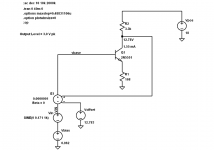
Hi Klaus,
Here is the simulation schematic that was used for single-stage CE BJT distortion as a function of either global NFB or NFB via emitter degeneration. I hope this answers your question. I think that the answer here is that what I am calling the global feedback is true voltage feedback.
Cheers,
Bob
Attachments
High-Order Distortion vs NFB
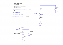
I should also point out that the last graph of distortion vs NFB with a fixed amount of emitter degeneration was done with slightly different circuit element values, as it was done at a different time. That simulation schematic is shown below. This illustrates the case of 6 dB of NFB loop gain around a stage that is degenerated by a factor of about 10:1.
Cheers,
Bob
Attachments
- Home
- Amplifiers
- Solid State
- Bob Cordell Interview: Negative Feedback